
High-speed forging machine two-way clutch brake device

A two-way clutch and brake technology, applied in the field of forging machinery, can solve the problems of not being able to meet the performance requirements of high-speed forging machinery, large parts and space, and consume more energy, and achieve rapid and reliable combination and separation, less transmission inertia, and space volume little effect

Inactive Publication Date: 2010-09-29
王建新
View PDF0 Cites 8 Cited by
  • Summary
  • Abstract
  • Description
  • Claims
  • Application Information

AI Technical Summary

Problems solved by technology

The main reason for this is that the existing clutch brakes all use pneumatic friction clutches. This type of clutch brake not only needs compressed air equipment, but at the same time, due to the complex structure of the clutch brake components, the volume of the entire component is relatively large. The inertia is also large, which requires more energy consumption. In addition, because the separation and combination of the clutch are carried out under the control of the mechanical system, and the speed of the mechanical movement is difficult to further increase under certain conditions, so this This kind of clutch brake not only has the defects of complex structure and large energy consumption, but especially cannot meet the performance requirements of high-speed forging machinery

Method used


Image

  • High-speed forging machine two-way clutch brake device
  • High-speed forging machine two-way clutch brake device

Examples


Embodiment Construction

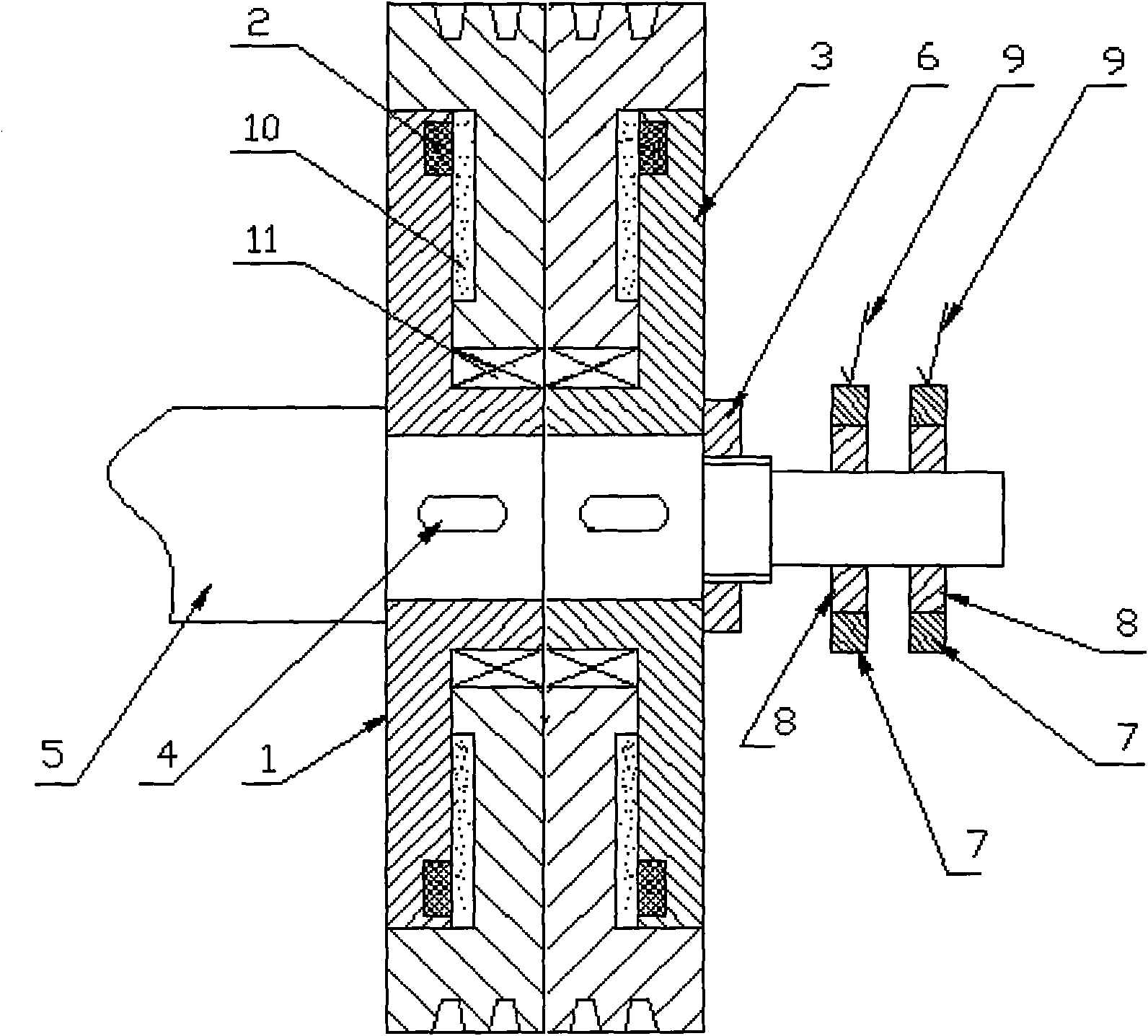
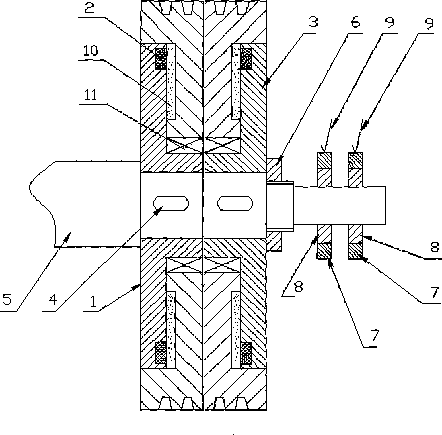
[0009] Described flywheel (1) is installed on the outer circle of the hollow shaft of drive disc (3) by bearing (11), and drive disc (3) is installed on one end of crankshaft (5) by the hollow shaft that is connected with it, and It is fixed to the crankshaft (5) by the key (4). An annular groove is formed on the opposite side of the drive disc (3) to the flywheel (1), and the coil (2) is installed in the groove. A closed space is formed between the opposite side of the driving disc (3) to the flywheel (1) and the flywheel (1), during which an appropriate amount of magnetic powder (10) is filled, in order to make the driving disc (3) and the flywheel (1) move When the position is fixed, the external thread is produced on the outer circle on the step at one end of the crankshaft (5), and the nut (6) is screwed on the external thread to fix the driving disc (3) and the flywheel (1) on the crankshaft (5). At one end of the crankshaft (5), two insulating rings (8) are respectivel...


PUM


Abstract

The invention relates to a high-speed forging machine two-way clutch brake device which has the technical scheme that a flywheel is installed on the excircle of a hollow shaft of a driving disc; the driving disc and the hollow shaft connected with the driving disc are installed at one end of a crankshaft which is fixed by a key; the driving disc is provided with a ring-shaped groove at the side relative to a flywheel, and the groove is provided with a coil; a closed space is formed by the flywheel and the side of the driving disc relative to a flywheel, and is filled with right amount of magnetic powder; in order to lead the positions of the driving disc and the flywheel to be fixed when in movement, the excircle on a step at one end of the crankshaft is provided with an external thread which is screwed with a nut for fixing the driving disc and the flywheel on the crankshaft; one end of the crankshaft is respectively provided with two insulating rings; the excircles of the insulating rings are respectively provided with two conducting rings; joints at the two ends of the coil are respectively connected with the conducting rings; and the excircle surfaces of the conducting rings are respectively provided with a conductive electrode, and elastic contact is formed between the two conducting rings and the conductive electrodes.

Description

technical field [0001] The invention relates to a clutch brake device, in particular to a bidirectional clutch brake device for high-speed forging machinery, which belongs to the technical field of forging machinery. Background technique [0002] With the development of forging technology and the requirements of stamping production, the working speed of forging machinery is getting higher and higher. With the increase of the working speed of forging machinery, the existing forging machinery clutch brakes are becoming less and less suitable for the performance requirements of high-speed forging machinery. The main reason for this is that the existing clutch brakes all use pneumatic friction clutches. This type of clutch brake not only needs compressed air equipment, but at the same time, due to the complex structure of the clutch brake components, the volume of the entire component is relatively large. The inertia is also large, which requires more energy consumption. In add...

Claims


Application Information

Patent Timeline
Patent Type & Authority Applications(China)
IPC IPC(8): B21J13/00F16D27/02
Inventor 王建新
Owner 王建新
Learn More