
Concentric magnetic gear using squirrel cage type magnetic field regulating device

A magnetic gear and squirrel-cage technology, applied to electrical components, generators/motors, etc., can solve problems such as reduced efficiency, reduced torque, and speed difference, and achieve the effect of improving processing performance and structural rigidity

Inactive Publication Date: 2010-09-22
JIANGSU UNIV
View PDF4 Cites 36 Cited by
  • Summary
  • Abstract
  • Description
  • Claims
  • Application Information

AI Technical Summary

Problems solved by technology

[0003] But this kind of concentric magnetic gear also has disadvantages. First, because there is a speed difference between the inner and outer rotors and the stator, in order not to affect the magnetic adjustment function of the stator and improve its transmission efficiency, the support parts of the stator adjustment magnet block are generally made of non-metallic materials. It is easy to cause the stiffness and machining accuracy of the stator to be difficult to meet the requirements. Secondly, due to the speed difference of each part of this magnetic gear, according to the law of electromagnetic induction, the efficiency will decrease during operation, and the torque will decrease. especially when

Method used


Image

  • Concentric magnetic gear using squirrel cage type magnetic field regulating device
  • Concentric magnetic gear using squirrel cage type magnetic field regulating device
  • Concentric magnetic gear using squirrel cage type magnetic field regulating device

Examples


Embodiment Construction

[0022] Form (3) is taken as an example below to further illustrate the structural scheme.

[0023] Form (3) specific implementation method:

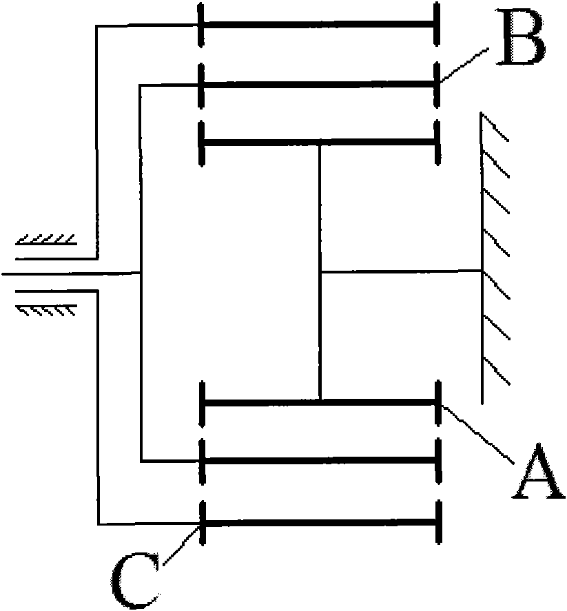
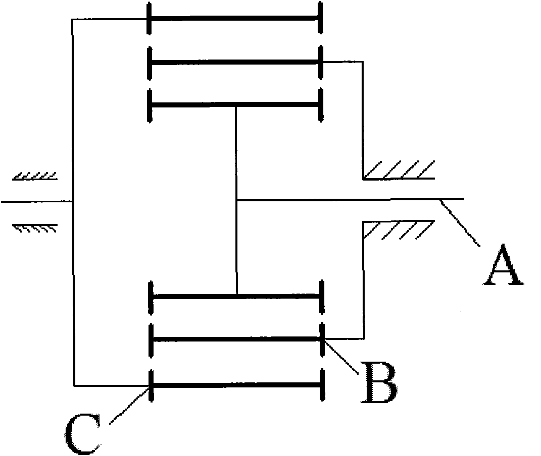
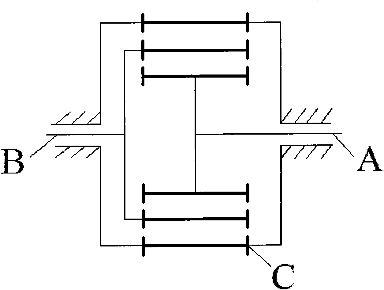
[0024] The overall structure is as Figure 4 As shown, the device includes: high-speed rotor assembly (I), low-speed rotor assembly (II) and stator assembly (III). Among them, the high-speed rotor assembly (I) is the internal permanent magnet structure (A), which is connected to the high-speed shaft through the flat key; the low-speed rotor assembly (II) is the middle magnetic adjustment structure (B), which is connected to the low-speed shaft through the flat key connection; the stator assembly (III) is the external permanent magnet structure (C), which is installed outside the structure.

[0025] The specific structure is: the high-speed rotor assembly (1) includes an inner rotor base body (8) and an inner rotor permanent magnet (7). The permanent magnets (7) of the inner rotor are closely arranged and bonded on the outer surface of...


PUM


Abstract

The invention discloses a concentric magnetic gear using a squirrel cage type magnetic field regulating device and relates to the technical field of engineering machine transmission. The gear is comprised of an internal permanent magnet structure, a middle magnetic filed regulating structure and an external permanent magnet structure, wherein the outside surface of the internal permanent magnet structure is provided with permanent magnets of which the N poles and S poles are arranged closely and alternately, and the number of the magnetic pole pairs is P1; the middle magnetic filed regulating structure is positioned between the internal permanent magnet structure and the external permanent magnet structure, a soft magnetic material is directly processed into to make a squirrel cage type structure or a combined squirrel cage type structure of a magnetic filed regulating block made of a nonconductive material and the soft magnetic material, and the number of cage bars is R; the inside surface of the external permanent magnet structure is provided with permanent magnets of which the N poles and S poles are arranged closely and alternately, and the number of the magnetic pole pairs is P2; and R is equal to the sum of the P1 and the P2. When the internal permanent magnet structure rotates, a rotary magnetic filed in which the number of the magnetic pole pairs is P1 is generated, the middle magnetic filed regulating structure modulates the rotary magnetic field into a rotary magnetic field in which the number of the magnetic pole pairs is P2, the rotation speed and direction of the rotary magnetic field in which the number of the magnetic pole pairs is P1 are changed at the same time to drive the external permanent magnet structure to rotate, and thus, the aim of changing the rotation speed is realized.

Description

technical field [0001] The invention relates to the technical field of transmission in mechanical engineering, in particular to a new type of concentric magnetic gear, which can be applied to a non-contact transmission system with large vibration, no leakage, and large torque for high and low speed transmission. Background technique [0002] In the field of magnetic transmission, there are not many applications of magnetic gears, mainly because the utilization rate of permanent magnets in traditional meshing magnetic gears is too low, and only the two adjacent magnetic poles play a role in the transmission of torque, resulting in the traditional magnetic gears. Torque density is very low. In response to this shortcoming, the British K.Atalla and D.Howe proposed a concentric magnetic gear. Permanent magnets are arranged on its inner and outer rotors. There is a stator between the two rotors. The stator is composed of a certain number of magnetic adjustment blocks along the T...

Claims


Application Information

Patent Timeline
IPC IPC(8): H02N11/00
Inventor 杨超君李直腾郑武蒋生发
Owner JIANGSU UNIV
Learn More