High frequency circuit radiation electromagnetic inference analysis method

A high-frequency circuit and electromagnetic interference technology, applied in the direction of electromagnetic field characteristics, can solve the problems of high cost of OATS or anechoic chamber, difficulty in popularization and application, and high price of near-field electromagnetic field measurement system

Inactive Publication Date: 2010-09-22
SOUTHEAST UNIV
View PDF5 Cites 5 Cited by
  • Summary
  • Abstract
  • Description
  • Claims
  • Application Information

AI Technical Summary

Problems solved by technology

[0003] The analysis of electromagnetic interference radiated by high-frequency circuits usually uses far-field measurement or near-field measurement. Among them, the far-field measurement method is the method of measuring the circuit under test by using open field (OATS) measurement or anechoic chamber (Anechoic chamber). But OATS or anechoic chamber is expensive and the construction period is long, and the measurement cost is high
Near-field measurement is to use a near-field electromagnetic field measurement system to measure the EMI of the circuit under test (such as the EMI TESTER series produced by HITACHI, etc.), but this type of system can only give the result of the radiation field strength of the circuit under test, but does not No statement can be given about the characteristics of these high-frequency circuits (i.e. whether the source of radiation is caused by electric or magnetic fields)
At the same time, the measurement method of this type of system is scanning measurement, that is, the entire area of ​​the high-frequency circuit needs to be scanned point by point, so the measurement process is time-consuming
In addition, the price of the above-mentioned near-field electromagnetic field measurement system is relatively expensive, and it is difficult to popularize and apply it.

Method used


Image

  • High frequency circuit radiation electromagnetic inference analysis method
  • High frequency circuit radiation electromagnetic inference analysis method
  • High frequency circuit radiation electromagnetic inference analysis method

Examples


Embodiment Construction

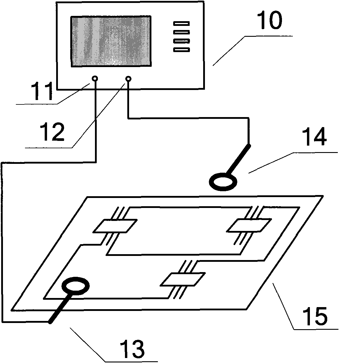
[0038] In order to illustrate the effectiveness of the present invention to high-frequency circuit radiation EMI analysis, the self-made radiation emission source is adopted as the circuit under test to implement, and the circuit is as follows Figure 5 shown. Among them, S1 is a square loop circuit with a loop area of ​​100cm 2 , the frequency source is a 10MHz crystal oscillator; S2 is a short straight antenna with a length of 5cm, and the frequency source is a 6MHz crystal oscillator; S3 is a ring circuit with a loop area of ​​9πcm 2 , the frequency source is a 12MHz crystal oscillator, and each radiation source is generated by a 5V DC power supply. According to formulas (3) and (4), it can be seen that the size of the common mode radiation is proportional to the equivalent antenna length d1, and the size of the differential mode radiation is proportional to the loop area dS, so S1 and S3 are differential mode radiation sources, and their radiation The emission is dominat...


PUM


Abstract

The invention discloses a high frequency circuit radiation electromagnetic inference analysis method. Two near field electric field probes or near field magnetic field probes of the same type are respectively connected with the two input ends of a digital dual-trace oscilloscope. The two near field probes are arranged in different positions to measure a high frequency circuit. Blind signal analysis is carried out on time domain signals obtained by the oscilloscope. A single radiation source in the high frequency circuit can be differentiated according to the signal analysis result. The near field electric field probes and the near field magnetic field probes are respectively connected with the input ends of a spectrum analyzer to measure the near field electric field and the near field magnetic field of the single radiation source and compare the size of the near field electric field and the near field magnetic field. In this way, whether the electromagnetic inference of each radiation source is caused by common mode radiation or difference mode can be known. The method saves time, is convenient and practical and can provide guidance for high frequency circuit radiation EMI suppression.

Description

technical field [0001] The present invention relates to a method for analyzing the characteristics of electromagnetic interference (EMI) radiated by high-frequency circuits, specifically searching and locating the EMI radiation source of the high-frequency circuit based on the blind signal analysis method, and performing characteristic diagnosis on the EMI radiation source according to the source location result , belonging to the field of electromagnetic compatibility technology. Background technique [0002] At present, the EMI problem of power electronic products is becoming more and more prominent. On the one hand, because high-frequency devices are widely used in products, on the other hand, due to the increasing complexity and miniaturization of products, high-frequency circuits Radiated EMI solutions are becoming increasingly important. However, there are many kinds of radiated EMI solutions that can be used in high-frequency circuits, and there are also various radi...

Claims


Application Information

Patent Timeline
Patent Type & Authority Applications(China)
IPC IPC(8): G01R29/08
Inventor 褚家美赵阳罗永超颜伟李世锦
Owner SOUTHEAST UNIV
Why Eureka
Try Eureka