Method for air separation by storing cold energy of liquefied natural gas
A liquefied natural gas and air separation technology, applied in the fields of air separation and liquefied natural gas cold energy storage, can solve problems such as impact and unstable utilization of cold energy, and achieve the effects of reducing energy consumption, reducing work costs, and improving work efficiency
- Summary
- Abstract
- Description
- Claims
- Application Information
AI Technical Summary
Problems solved by technology
Method used
Image

Examples
Embodiment 1
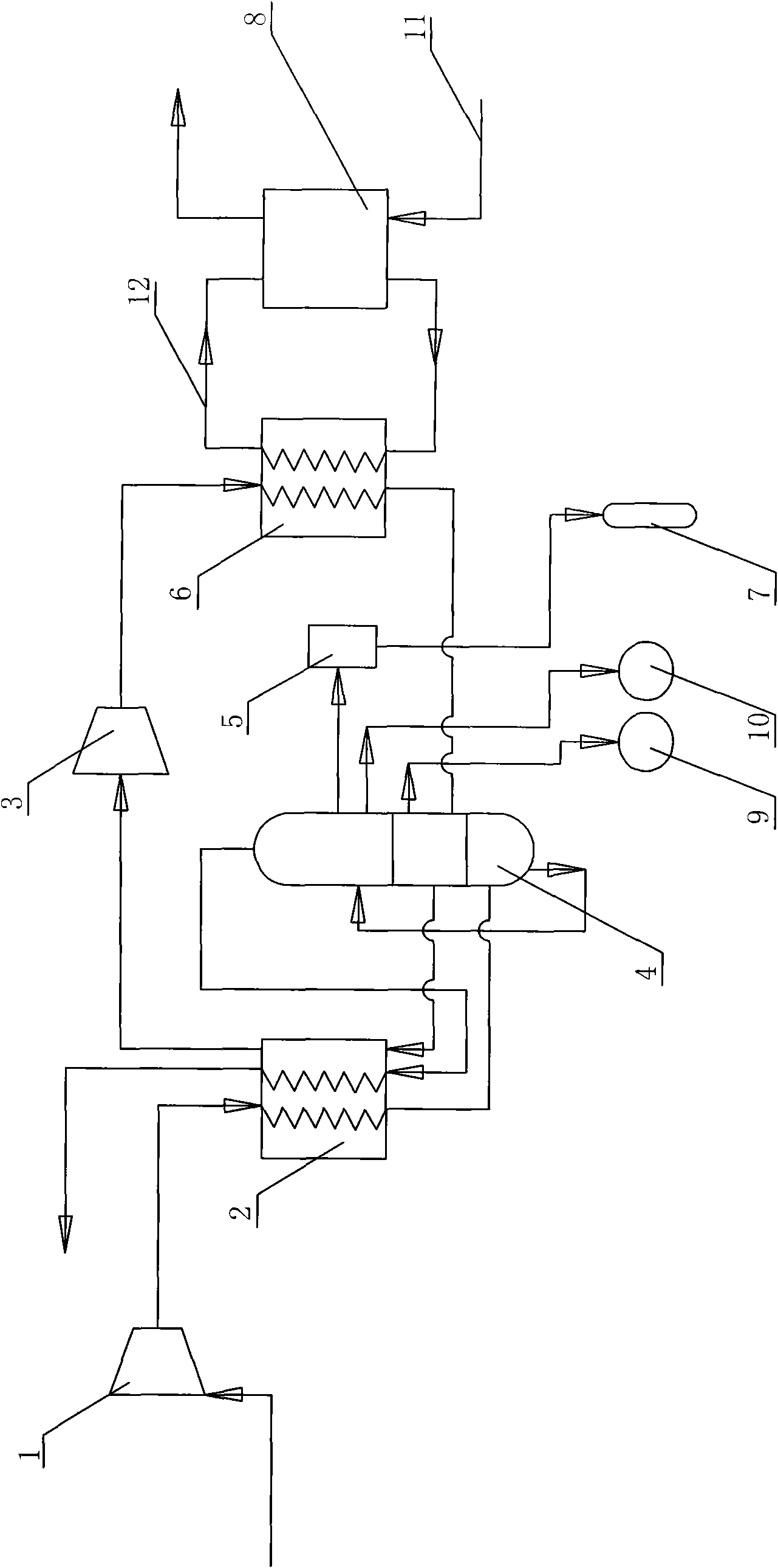
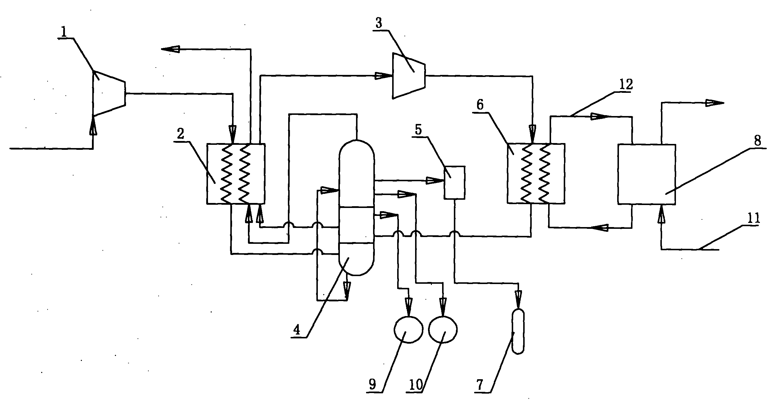
[0014] The air compressor 1 is communicated with the heat exchanger one 2 through pipelines; one side of the rectification column 4 is communicated with the heat exchanger one 2, and the other side is communicated with the heat exchanger two 6; the heat exchanger one 2 and the heat exchanger A circulating nitrogen compressor 3 is arranged on the pipeline communicated between the two 6, and the rectifying tower 4 is connected with the argon tower 5, the liquid oxygen storage tank 7, and the liquid nitrogen storage tank respectively through the pipeline 9; the argon tower 5 is connected with the liquid argon storage tank through the pipeline. The tank 10 is in communication; the heat exchanger 2 6 is in communication with the cold storage tank 8 through the brine pipeline 12 , and the cold storage tank 8 is in communication with the liquefied natural gas pipeline 11 .
[0015] Wherein the brine in the brine pipeline 12 is Freon R22, and the cool storage agent in the cold storage ...
Embodiment 2
[0017] The air compressor 1 is communicated with the heat exchanger one 2 through pipelines; one side of the rectification column 4 is communicated with the heat exchanger one 2, and the other side is communicated with the heat exchanger two 6; the heat exchanger one 2 and the heat exchanger A circulating nitrogen compressor 3 is arranged on the pipeline communicated between the two 6, and the rectifying tower 4 is connected with the argon tower 5, the liquid oxygen storage tank 7, and the liquid nitrogen storage tank respectively through the pipeline 9; the argon tower 5 is connected with the liquid argon storage tank through the pipeline. The tank 10 is in communication; the heat exchanger 2 6 is in communication with the cold storage tank 8 through the brine pipeline 12 , and the cold storage tank 8 is in communication with the liquefied natural gas pipeline 11 .
[0018] Wherein the brine in the brine pipeline 12 is 30% methanol solution, and the cool storage agent in the c...
Embodiment 3
[0020] The air compressor 1 is communicated with the heat exchanger one 2 through pipelines; one side of the rectification column 4 is communicated with the heat exchanger one 2, and the other side is communicated with the heat exchanger two 6; the heat exchanger one 2 and the heat exchanger A circulating nitrogen compressor 3 is arranged on the pipeline communicated between the two 6, and the rectifying tower 4 is connected with the argon tower 5, the liquid oxygen storage tank 7, and the liquid nitrogen storage tank respectively through the pipeline 9; the argon tower 5 is connected with the liquid argon storage tank through the pipeline. The tank 10 is in communication; the heat exchanger 2 6 is in communication with the cold storage tank 8 through the brine pipeline 12 , and the cold storage tank 8 is in communication with the liquefied natural gas pipeline 11 .
[0021] Wherein the brine in the brine pipeline 12 is dichloromethane, and the cool storage agent in the cold st...
PUM
 Abstract
Description
Claims
Application Information
 - R&D
- Intellectual Property
- Life Sciences
- Materials
- Tech Scout
- Unparalleled Data Quality
- Higher Quality Content
- 60% Fewer Hallucinations
Browse by: Latest US Patents, China's latest patents, Technical Efficacy Thesaurus, Application Domain, Technology Topic, Popular Technical Reports.
© 2025 PatSnap. All rights reserved.Legal|Privacy policy|Modern Slavery Act Transparency Statement|Sitemap|About US| Contact US: help@patsnap.com