Eureka AIR delivers breakthrough ideas for toughest innovation challenges, trusted by R&D personnel around the world.

Multi-module terminal circuit and multi-module terminal

A multi-mode terminal and circuit technology, applied in the field of communication, can solve the problems of large occupied area and high cost of multi-mode terminals, and achieve the effect of saving cost and reducing the occupied area

Active Publication Date: 2010-09-08
HUAWEI DEVICE CO LTD
View PDF3 Cites 33 Cited by
  • Summary
  • Abstract
  • Description
  • Claims
  • Application Information

AI Technical Summary

Problems solved by technology

[0006] The embodiment of the present invention provides a multi-mode terminal circuit and a multi-mode terminal, which are used to solve the defects of high cost and large occupied area of ​​the multi-mode terminal in the prior art, reduce the cost of the multi-mode terminal circuit, and reduce the occupation of the multi-mode terminal circuit area

Method used


Image

  • Multi-module terminal circuit and multi-module terminal
  • Multi-module terminal circuit and multi-module terminal
  • Multi-module terminal circuit and multi-module terminal

Examples


Embodiment 1

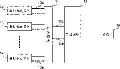
[0020] Some sub-frequency bands divided in different communication standards may be the same, and the receiving and sending frequencies of various communication systems in this sub-frequency band are the same, so for different communication standards, many radio frequency components can be shared. Table 1 shows the distribution of sub-frequency bands in the two communication systems of Wideband Code-Division Multiple Access (WCDMA for short) and Code-Division Multiple Access (CDMA for short).

[0021] Table 1. Distribution of sub-frequency bands in the two communication systems of WCDMA and CDMA

[0022]

[0023] It can be seen from Table 1 that the transceiver frequencies of WCDMA sub-band 1 and CDMA sub-band 6 are the same, so in these two sub-bands, the front-end used for signal processing of the signals sent by the WCDMA radio frequency transceiver chip and the CDMA radio frequency transceiver chip Modules can be shared. In various embodiments of the present invention,...

Embodiment 2

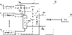
[0035] Such as figure 2 Shown is a schematic structural diagram of Embodiment 2 of the multimode terminal circuit of the present invention. In the multimode terminal circuit, the switch module 11 includes a first switch 111 and a second switch 112 . The first switch 111 is respectively connected with n radio frequency transceiver chips through n first uplinks 13a, and the first switch 111 is connected with the front-end module 12 through the second uplink 15a respectively; The uplink 13b is connected to n radio frequency transceiver chips 14, and the second switch 112 is connected to the front-end module 12 through the second downlink 15b; both the first switch and the second switch are 1-of-n switches.

[0036]In the second embodiment of the multi-mode terminal circuit, the first switch is mainly used to send the signals sent by the n radio frequency transceiver chips to the front-end module through the first uplink, and the second switch is mainly used to send the front-end...

Embodiment 3

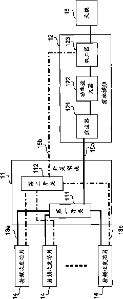
[0041] Such as image 3 Shown is a schematic structural diagram of Embodiment 3 of the multimode terminal circuit of the present invention. In this embodiment, the front-end module 12 includes a filter 121 , a power amplifier 122 and a duplexer 123 . The filter 121 is connected to the first switch 111 through the second uplink 15a, the power amplifier 122 is connected to the filter 121 and the duplexer 123 respectively, and the duplexer 123 is connected to the second switch 112 through the second downlink 15b, and the duplexer The device 123 is also connected to the antenna 16.


PUM


Abstract

The invention provides a multi-module terminal circuit and a multi-module terminal. The multi-module terminal circuit comprises n radio frequency transceiver chips, an antenna, a switch module and a front-end module, wherein the switch module is connected with the n radio frequency transceiver chips through a first uplink and a first downlink respectively, the front-end module is connected with the switch module through a second uplink and a second downlink respectively and is also connected with the antenna; signals transmitted by the n radio frequency transceiver chips are sent to the front-end module through the first uplink, or signals transmitted by the front-end module are received through the first downlink; after processing the signals transmitted by the switch module, the front-end module sends the processed signals to the antenna through the send uplink, or sends the signals received from the antenna to the switch module through the second downlink; and 'n' is a natural number larger than or equal to 2. The multi-module terminal circuit and the multi-module terminal provided by the invention have the advantages of saved cost and reduced area occupied by the multi-module terminal circuit.

Description

technical field [0001] Embodiments of the present invention relate to communication technologies, and in particular to a multi-mode terminal circuit and a multi-mode terminal. Background technique [0002] In the communication field, there are various communication standards, and different operators may adopt different communication standards, thus producing some multi-mode terminals, one multi-mode terminal can be applicable to different communication networks. [0003] A dual-mode terminal circuit in the prior art usually has the following structure: the first radio frequency transceiver chip is connected to the first front-end module, the second radio frequency transceiver chip is connected to the second front-end module, the first front-end module and the second front-end The modules are all connected with the switch, and the switch is connected with the antenna. The switch is used to select the current communication system. For example, if the communication standard c...

Claims


Application Information

Patent Timeline
Patent Type & Authority Applications(China)
IPC IPC(8): H04B1/38H04W88/06
Inventor 邱丹
Owner HUAWEI DEVICE CO LTD
Why Eureka
Eureka Blog
Learn More