Modularized longitudinal magnetic field permanent magnet motor

A longitudinal magnetic field, permanent magnet motor technology, applied in electrical components, electromechanical devices, electric components, etc., can solve the problems of complex structure of the core unit, improve current control accuracy and system reliability, simple manufacturing process, and simplified structure. Effect

Active Publication Date: 2012-06-27
HARBIN INST OF TECH
View PDF5 Cites 0 Cited by
  • Summary
  • Abstract
  • Description
  • Claims
  • Application Information

AI Technical Summary

Problems solved by technology

[0005] In order to solve the problem of complex core unit structure, reduce the shortcoming of winding copper loss, and achieve the effect of eliminating magnetic coupling between phases in the original structure, the present invention proposes a modular longitudinal magnetic field permanent magnet motor

Method used


Image

  • Modularized longitudinal magnetic field permanent magnet motor
  • Modularized longitudinal magnetic field permanent magnet motor
  • Modularized longitudinal magnetic field permanent magnet motor

Examples


specific Embodiment approach 1

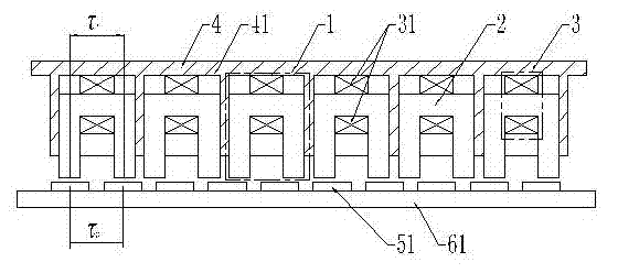
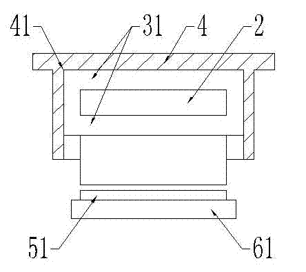
[0010] Specific implementation mode one: combine Figure 1 to Figure 5 Describe this embodiment, the motor of this embodiment is a flat linear motor consisting of a primary and a secondary, with an air gap between the primary and the secondary; the primary is composed of a phase unit fixed housing 4 and several phase units 1; the phase unit The fixed housing 4 is a flat plate, and the lower surface of the phase unit fixed housing 4 is equally spaced with square fixing holes 41 along the moving direction. The number of the square fixing holes 41 is the same as that of the phase unit 1, and each square fixing hole 41 Each phase unit 1 is fixedly installed; each phase unit 1 is composed of a core unit 2 and a phase unit winding 3; the core unit 2 is composed of two teeth and a yoke segment 21; the yoke segment 21 It is located between the two teeth, and the yoke segment 21 and the two teeth are connected in the shape of a door along the moving direction, that is, the two teeth ar...

specific Embodiment approach 2

[0011] Specific implementation mode two: combination figure 1 and figure 2This embodiment is described. The first difference between this embodiment and the specific embodiment is that the phase unit winding 3 is composed of a coil 31 , and the coil 31 is wound on the yoke segment 21 of the core unit 2 . Other compositions and connection methods are the same as those in Embodiment 1.

specific Embodiment approach 3

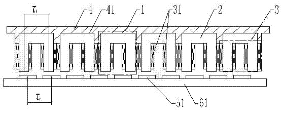
[0012] Specific implementation mode three: combination image 3 and Figure 4 Describe this embodiment, the difference between this embodiment and the specific embodiment is that the phase unit winding 3 is composed of two coils 31, and the two coils 31 are respectively wound on the two teeth of the core unit 2, and the two The coils 31 are wound in opposite directions, and the two coils 31 are connected in series. Other compositions and connection methods are the same as those in Embodiment 1.


PUM


Abstract

The invention discloses a modularized longitudinal magnetic field permanent magnet motor, relating to the motor field, solving the problem of complex structure of an iron core unit, reducing winding copper loss and achieving the effect of eliminating interphase magnetic coupling of the original structure. Each fixing hole of a phase unit fixing shell is fixed with a phase unit, the iron core in each phase unit consists of two teeth and a magnetic yoke segment which is arranged between the two teeth and is connected into an n shape along the movement direction, the phase unit winding is wound on the iron core unit; the secondary comprises permanent magnets and a magnetic yoke; the permanent magnets are fixed on the magnetic yoke, magnetizing directions of each two adjacent permanent magnetare opposite, or the permanent magnets are in a Halbach magnet structure; the pitch of two teeth of the iron core unit and the polar distance of the permanent magnets meet the relationship of tau t>tau p, the pitch tau l of two adjacent teeth in different phase units and the polar distance of the permanent magnets meet the relationship of tau l<tau p, and tau t, tau l and tau p meet the relationship of mk1 (tau t + tau l) = (mk2+ / -1) tau p. The permanent magnet motor of the invention adopts special phase units and can be widely used for other types of motors.

Description

technical field [0001] The invention relates to the field of electrical machines. Background technique [0002] The structure of the traditional flat linear permanent magnet synchronous motor is as follows: Figure 9 shown. The motor has an integer slot structure, that is, the number of slots per pole and phase of the motor is an integer. The main problems of the linear permanent magnet synchronous motor with integer slot structure are: on the one hand, the positioning force of the motor caused by the cogging effect is relatively large; on the other hand, the performance-to-volume ratio of the motor is low, which is mainly due to the p When the design is large, the yoke part of the permanent magnet will be thickened, which will increase the volume and weight of the motor, and when the pole pitch of the motor τ p If the design is small, the armature core pitch τ t is small, which reduces the strength of the armature teeth, i.e. the pitch τ of the motor t and polar distanc...

Claims


Application Information

Patent Timeline
Patent Type & Authority Patents(China)
IPC IPC(8): H02K41/02
Inventor 寇宝泉张赫
Owner HARBIN INST OF TECH
Why Eureka
Try Eureka