Flexible combined oil pump plunger piston
An oil pump and plunger technology, which is applied in the field of petroleum machinery exploitation, can solve the problems of high machining precision, high leakage, and increase the downward resistance of the plunger, so as to prolong the effective sealing period, prolong the service life, reduce the The effect of severe wear
- Summary
- Abstract
- Description
- Claims
- Application Information
AI Technical Summary
Problems solved by technology
Method used
Image
Examples
Embodiment 1
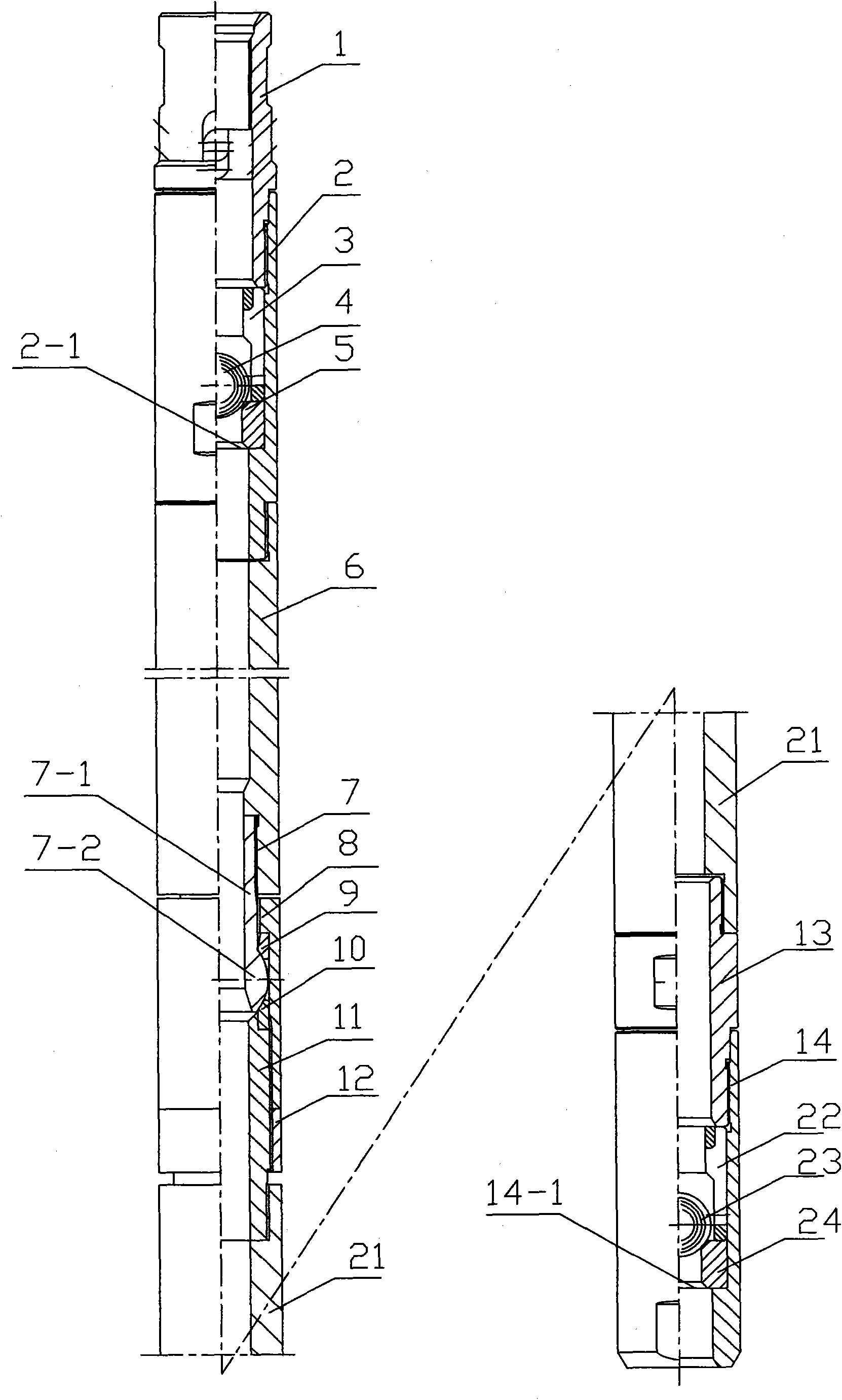
[0025] Such as figure 1 As shown, there are two rigidly combined oil well pump plungers, including an upstream traveling valve, an upper plunger body 6, a flexible connector, a lower plunger body 18 and a lower traveling valve.
[0026] The upstream floating valve includes an upper joint 1, an upper valve housing 2, an upper valve cover 3, an upper valve ball 4 and an upper valve ball seat 5, the upper valve housing 2 is threadedly connected to the lower end of the upper joint 1, and the inner diameter of the upper valve housing 2 Fix the upper boss 2-1, install the upper valve ball seat 5, the upper valve ball 4 and the upper valve cover 3 sequentially above the upper boss 2-1, and the upper end of the upper valve cover 3 is pressed against the lower end of the upper joint 1 . The lower end of the upper valve casing 2 is threadedly connected to the upper plunger body 6 .
[0027] The flexible connector includes a ball connecting pipe 7 , a ball pressing cap 8 , a ball upper...
Embodiment 2
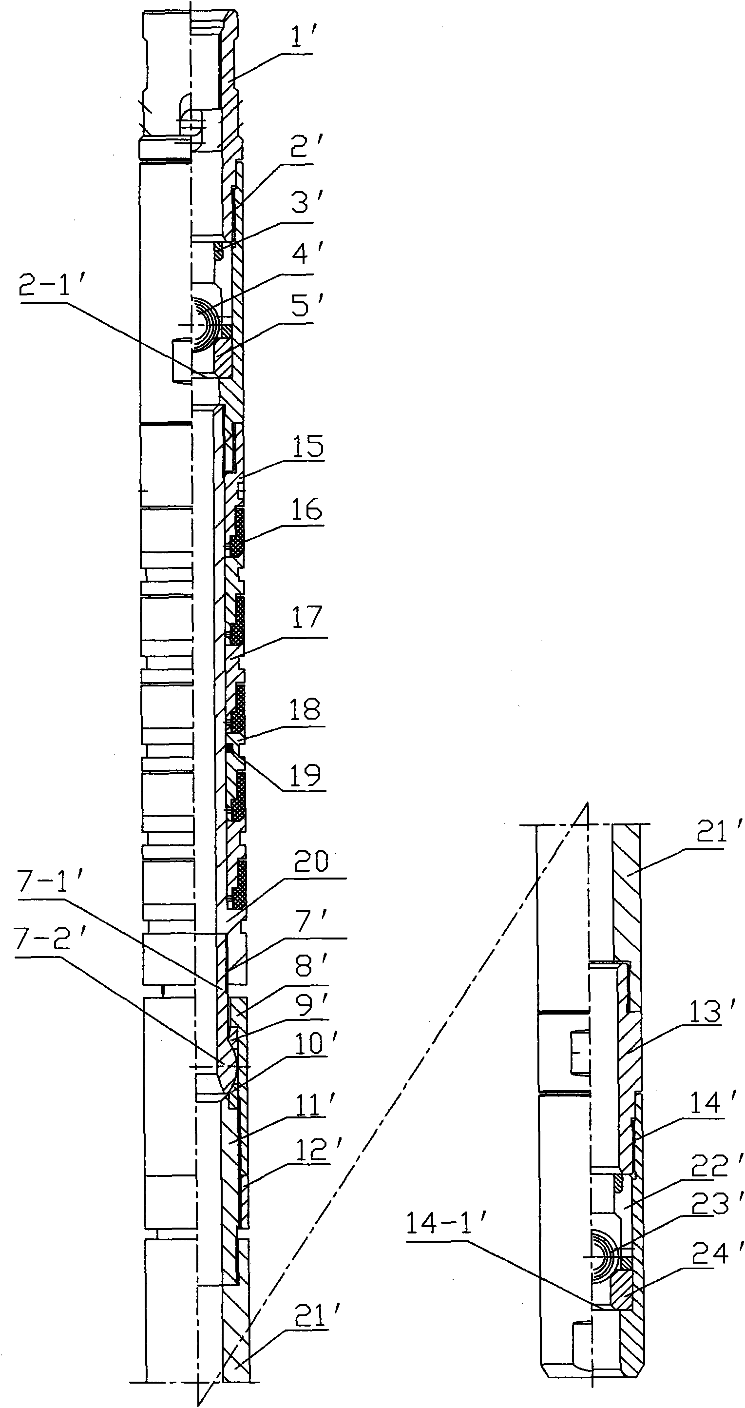
[0031] Such as figure 2 As shown, it is a rigid-flexible combined oil well pump plunger, including an upper floating valve, an upper soft sealing segment sealing body, a flexible connector, a lower plunger body 21' and a lower floating valve.
[0032] The upstream floating valve includes an upper joint 1', an upper valve housing 2', an upper valve cover 3', an upper valve ball 4' and an upper valve ball seat 5', and the upper valve housing 2' is threadedly connected to the lower end of the upper joint 1', The inner side of the upper valve casing 2' radially fixes the upper boss 2-1', and the upper part of the upper boss 2-1' is sequentially loaded with the upper valve ball seat 5', the upper valve ball 4' and the upper valve cover 3', and the upper The upper end of the valve cover 3' is pressed against the lower end of the upper joint 1'. The lower end of the upper valve casing 2 ′ is internally threaded to the central pipe 20 , and the lower end of the upper valve casing 2 ...
PUM
 Abstract
Description
Claims
Application Information
 - R&D
- Intellectual Property
- Life Sciences
- Materials
- Tech Scout
- Unparalleled Data Quality
- Higher Quality Content
- 60% Fewer Hallucinations
Browse by: Latest US Patents, China's latest patents, Technical Efficacy Thesaurus, Application Domain, Technology Topic, Popular Technical Reports.
© 2025 PatSnap. All rights reserved.Legal|Privacy policy|Modern Slavery Act Transparency Statement|Sitemap|About US| Contact US: help@patsnap.com


