
Automatic pupilometer with visual check

A pupil meter, automatic technology, used in equipment for testing eyes, medical science, diagnosis, etc.

Active Publication Date: 2010-09-01
ESSILOR INT CIE GEN DOPTIQUE
View PDF2 Cites 2 Cited by
  • Summary
  • Abstract
  • Description
  • Claims
  • Application Information

AI Technical Summary

Problems solved by technology

[0014] The invention solves the problem of accurate positioning of the eyes of the calibration individual in the automatic pupillometer

Method used


Image

  • Automatic pupilometer with visual check
  • Automatic pupilometer with visual check
  • Automatic pupilometer with visual check

Examples


Embodiment Construction

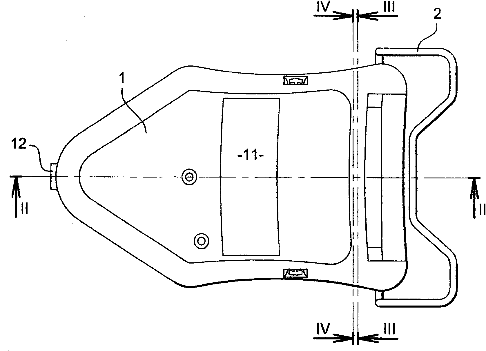
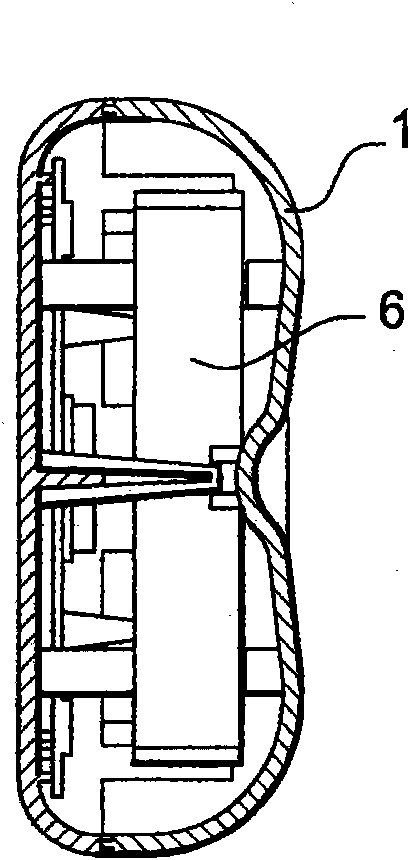
[0034] Figure 1-4 An automatic pupillometer according to the invention is shown in detail in .

[0035] The pupillometer comprises a housing 1 provided with a part 2 reproducing a spectacle frame placed on the nose of the individual whose interpupillary distance is to be measured.

[0036] Inside the housing, the automatic pupillometer includes:

[0037] an infrared light source 3 adapted to generate a corneal reflection on at least one eye of the individual, both eyes facing the first or second window 4, respectively;

[0038] · Visible light source 5, which is placed next to the infrared light source and is intended to be viewed and fixed by the individual;

[0039] a collimating lens 6 for at least positioning the light sources 3, 5 so that, corresponding to the individual's farsightedness, the infrared light source 3 and the visible light source 5 are located near the focal point of the lens 6;

[0040] a detection receiver consisting of a camera 7 for automatic positi...


PUM


Abstract

The invention relates to an automatic pupilometer that comprises a light source (3) capable of generating a corneal reflection on at least one of the eyes of an individual each placed in front of a first and a second window (4), a collimation lens (6) for at least positioning the light source so as to correspond to the distance vision of the individual, a detection receptor (7) for automatically locating the reflection, and a calculator for calculating the pupil deviation of said individual. According to the invention, the pupilometer further includes a third window (12) in which the eye of an observer responsible for the measurement is to be placed in the vicinity of the focus of said lens (6) in order to display and check the measurement conditions.

Description

technical field [0001] The present invention relates to an automatic pupillometer with visual verification. Background technique [0002] A pupillometer is a device designed to measure the interpupillary distance of an individual. It involves utilizing a light source adapted to produce a corneal reflection on at least one eye of the individual, and then localizing the reflection. [0003] The pupillometer may be manual, for example the pupillometer described in patent document FR1506352. [0004] The device is provided with three windows, two of which reproduce the spectacle frames placed on the individual's nose, and the opposite window where the eyes of the observer responsible for the measurement are located is placed at the focal point of the collimating lens so that the light source is located beyond infinity. Corresponds to the hypermetropia of the individual. The lens can be moved in translation along the boresight axis, enabling nearsightedness measurements; the l...

Claims


Application Information

Patent Timeline
Patent Type & Authority Applications(China)
IPC IPC(8): A61B3/11
CPCA61B3/111
Inventor M·诺彻
Owner ESSILOR INT CIE GEN DOPTIQUE
Learn More