
Three-phase rectifier for realizing current distribution by utilizing auxiliary bridge feedback

A three-phase rectifier and current distribution technology, applied in the direction of converting irreversible AC power input to DC power output, etc., can solve complex problems and achieve the effect of low cost, simple and reliable circuit

Inactive Publication Date: 2012-06-27
汪槱生
View PDF0 Cites 0 Cited by
  • Summary
  • Abstract
  • Description
  • Claims
  • Application Information

AI Technical Summary

Problems solved by technology

Although the voltage of the two thyristor rectifiers can be adjusted, it is more complicated to ensure that the two rectifiers share the current and completely eliminate the 5th, 7th, ... and other harmonics under different voltage and load changes.

Method used


Image

  • Three-phase rectifier for realizing current distribution by utilizing auxiliary bridge feedback
  • Three-phase rectifier for realizing current distribution by utilizing auxiliary bridge feedback
  • Three-phase rectifier for realizing current distribution by utilizing auxiliary bridge feedback

Examples


Embodiment Construction

[0013] Below in conjunction with specific embodiment the present invention is described in further detail:

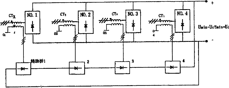
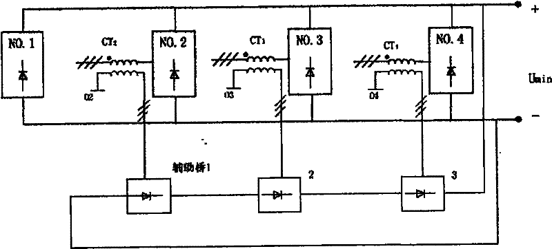
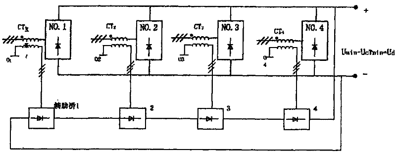
[0014] In this embodiment, the three-phase rectifier that uses auxiliary bridge feedback to reduce voltage at the input end to achieve current sharing is as follows: figure 1 As shown in , there are 4 sets of main rectifiers N0.1~N0.4 as a complete set of rectifiers and they are connected in parallel; and the turn ratio of the 4 sets is n 1 : n 2 Each current transformer is connected to the input terminal of a main rectifier, and the output terminal of each current transformer is connected to an auxiliary rectifier; after the auxiliary rectifiers are connected in series, they are connected in parallel to the main rectifier in parallel. Both ends of the rectifier output; where, n 1 / n 2 ≥(k-1)×ΔU / U min , where U min It is the voltage of the one with the smallest output voltage among the k main rectifiers under the rated load when not connected in parallel, ΔU is the...


PUM


Abstract

The invention relates to a rectifying technology in the field of power electronics, aiming at providing a three-phase rectifier for realizing current distribution by utilizing auxiliary bridge feedback. The three-phase rectifier comprises k numbered main rectifiers connected in parallel, and k numbered current transformers, wherein the current transformers are respectively connected to the input ends of the main rectifiers, the output ends of the current transformer are respectively connected with three-phase diode rectifiers serving as auxiliary rectifiers; and the auxiliary rectifiers are mutually connected in series, and then are connected in parallel to both ends of the output ends of the main rectifiers connected in parallel. In the invention, the three-phase rectifier of the invention does not need active devices in the process of realizing current distribution, the circuit is simple and reliable, the cost is low; and particularly, the invention can automatically keep current equalization along with the change of loads. Meanwhile, the main rectifiers distribute currents according to a certain ratio rather than a current equalization mode according to the difference of turn ratios of the current transformers matched with the main rectifiers, thereby adapting to the demands of different conditions.

Description

technical field [0001] The invention relates to the rectification technology in the technical field of power electronics, and more specifically, the invention relates to a three-phase rectifier which utilizes auxiliary bridge feedback to realize current distribution. Background technique [0002] In order to reduce the pollution of the harmonic wave generated by the rectifier to the power grid, multiple rectifiers are often used. For example, two rectifiers powered by a Y-connection power supply and a Δ-connection power supply can eliminate the 5th and 7th harmonics (hereinafter referred to as No. 1 and No. 2 units, and so on for more No. 1 units). When the rectified voltage is not high, the outputs of these two rectifiers are often connected in parallel. Parallel connection requires current sharing, but the commonly used diode rectifier itself has no current sharing capability, and the two rectifiers do not have the ability to adjust current sharing when a common voltage r...

Claims


Application Information

Patent Timeline
Patent Type & Authority Patents(China)
IPC IPC(8): H02M7/04
Inventor 汪槱生
Owner 汪槱生
Learn More