
Spiral transmission positioning device

A positioning device, screw drive technology, applied in the direction of transmission, belt/chain/gear, mechanical equipment, etc., can solve problems such as restriction, locking, and inability to work

Active Publication Date: 2012-02-08
彭中
View PDF0 Cites 0 Cited by
  • Summary
  • Abstract
  • Description
  • Claims
  • Application Information

AI Technical Summary

Problems solved by technology

[0002] There are many structures of existing reciprocating linear motion devices. The more commonly used one is to use the screw between the screw and the nut to realize linear transmission. The nut on the screw rod moves linearly, but the positioning of the nut linear motion is a difficult problem. When the nut moves to the stopper on one side of the screw rod, it is easy to lock up, that is, the nut and the stopper are locked, and the locking force is often greater than the rotation of the motor. unable to work
In the prior art, in order to overcome this problem, a high-precision, high-cost stepper motor or servo motor is used to control the number of turns of the screw, so that the nut does not come into contact with the stopper to prevent the two from being locked. Due to the high cost and large size of the stepping motor and the supporting control chip, the application of the screw drive positioning device is restricted

Method used


Image

  • Spiral transmission positioning device
  • Spiral transmission positioning device
  • Spiral transmission positioning device

Examples


Embodiment Construction

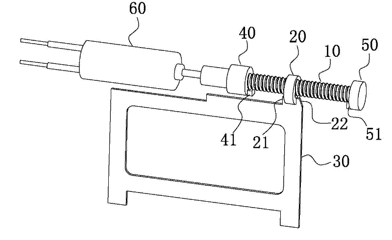
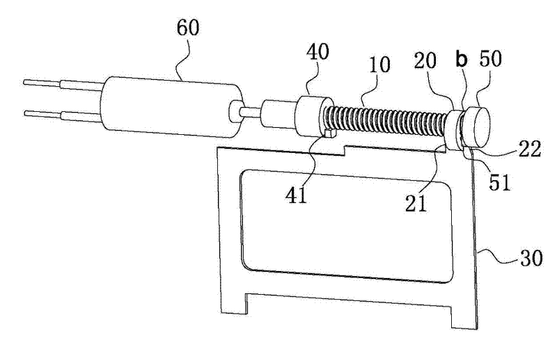
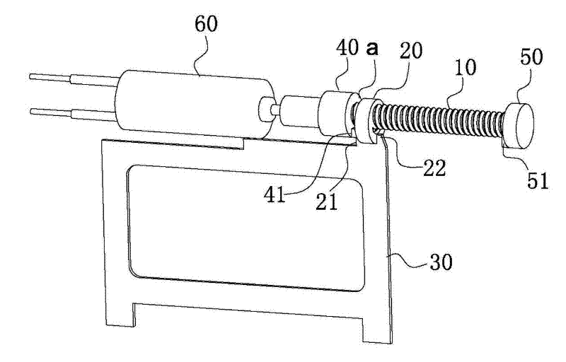
[0015] Such as Figure 1-3 As shown, a screw drive positioning device includes: a screw rod 10, a drive nut 20, a linear reciprocating mechanism 30 fixed together with the drive nut 20, the drive nut 20 is threaded on the screw rod 10 and the drive nut 20 is radially Fixed, at the left and right ends of the screw rod 10, a left limit stop 40 and a right limit stop 50 are respectively fixed;

[0016] One end of the screw 10 is fixedly connected to the output end of the motor 60, and the control circuit that provides the motor 60 pulse current to control the intermittent or continuous forward and reverse rotation of the motor is connected to the motor 60 according to the set time; the left and right sides of the drive nut 20 are respectively A left positioning protrusion 21 and a right positioning protrusion 22 are provided; the left limit stopper 40 is provided with a rotating protrusion 41 deviated from the axis of the screw rod 10, and the left rotating protrusion 41 and the ...


PUM


Abstract

The invention relates to a spiral transmission positioning device capable of preventing the self-locking phenomenon of a nut and a screw by adopting a common motor. The device comprises the screw, a transmission nut and a linear reciprocating motion mechanism; a left limit stop and a right limit stop are fixed on the left and right sides of the screw; and the lateral surface of a left rotating convex position on the screw is rotationally propped on the lateral surface of a left positioning convex position on the transmission nut to stop rotating so as to realize positioning of the screw and the transmission nut, and then the nut and the left limit stop have an anti-locking clearance, thus, the screw and the transmission nut cannot be locked, and the position device can work easily throughmotor inversion. Therefore, connective linear reciprocating motion can be realized by emitting discontinuous or continuous pulse current in a set time to control the positive and negative rotation ofthe motor through a common direct-current motor or a common alternating-current motor.

Description

technical field [0001] The invention relates to a screw transmission positioning device in the mechanical field, in particular to a screw transmission positioning device which can prevent the self-locking phenomenon of a nut and a screw rod by using an ordinary motor. Background technique [0002] There are many structures of existing reciprocating linear motion devices. The more commonly used one is to use the screw between the screw and the nut to realize linear transmission. The nut on the screw rod moves linearly, but the positioning of the nut linear motion is a difficult problem. When the nut moves to the stopper on one side of the screw rod, it is easy to lock up, that is, the nut and the stopper are locked, and the locking force is often greater than the rotation of the motor. unable to work. In the prior art, in order to overcome this problem, a high-precision, high-cost stepper motor or servo motor is used to control the number of turns of the screw, so that the n...

Claims


Application Information

Patent Timeline
Patent Type & Authority Patents(China)
IPC IPC(8): F16H25/20F16H25/24
Inventor 彭中
Owner 彭中
Learn More