Transversal magnetic flux variable-reluctance permanent magnet motor

A technology of permanent magnet motor and transverse flux, applied in the direction of electrical components, electromechanical devices, electric components, etc., can solve the problems of complex secondary structure, reliability and low accuracy of current control, and achieve high accuracy of current control and light weight , the effect of improving efficiency

Inactive Publication Date: 2010-08-18
HARBIN INST OF TECH
View PDF8 Cites 8 Cited by
  • Summary
  • Abstract
  • Description
  • Claims
  • Application Information

AI Technical Summary

Problems solved by technology

[0005] In order to solve the problems of complex secondary structure, low reliability and low current control precision, the present invention proposes a transverse flux variable reluctance permanent magnet motor

Method used


Image

  • Transversal magnetic flux variable-reluctance permanent magnet motor
  • Transversal magnetic flux variable-reluctance permanent magnet motor
  • Transversal magnetic flux variable-reluctance permanent magnet motor

Examples


specific Embodiment approach 1

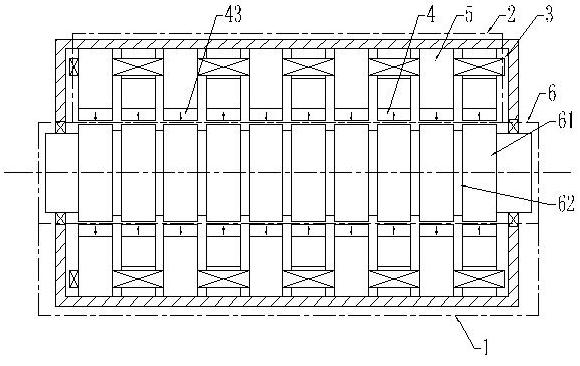
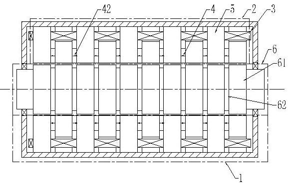
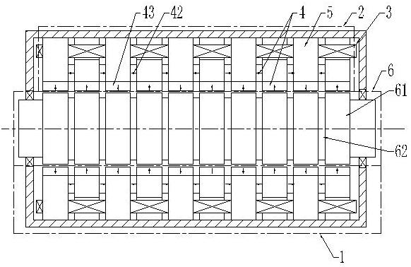
[0009] Embodiment 1: Combining Figure 1 to Figure 27 Illustrating this embodiment, this embodiment is composed of a primary and a secondary, with an air gap between the primary and the secondary; the secondary 6 includes a secondary core 61; the primary is composed of at least one phase unit 1; each phase unit 1 is composed of a phase The unit iron core 2, the phase unit winding 3 and the permanent magnet 4 are composed; the phase unit iron core 2 is composed of several iron core units 5 to form a phase unit iron core with a tooth hole 71, and the tooth hole 71 is composed of several iron core units 5 The tooth slots 72 are alternately superimposed, the permanent magnets 4 are arranged on the teeth of the iron core unit 5, and the magnetic fields generated by the permanent magnets 4 located on the teeth of the adjacent iron core units 5 have opposite directions; the coil 31 passes through the phase unit The tooth holes 71 of the iron core 2 are wound into a phase-phase unit w...

specific Embodiment approach 2

[0010] Specific implementation mode 2: Combining figure 1 , Figure 4 , Image 6 , Figure 9 , Figure 12 , Figure 14 , Figure 15 , Figure 18 , Figure 19 and Figure 22 to Figure 27 Describing this embodiment, the difference between this embodiment and the specific embodiment 1 lies in that each tooth end of the iron core unit 5 is provided with a permanent magnet 4 . Other compositions and connection methods are the same as those in the first embodiment. The permanent magnet 4 is fixed on the tooth end by sticking, and the permanent magnet 4 is stuck on the tooth surface of the iron core unit 5 facing the air gap.

specific Embodiment approach 3

[0011] Specific implementation three: combination figure 2 , Figure 5 , Figure 10 and Figure 13 Describing this embodiment, the difference between this embodiment and the specific embodiment 1 lies in that a permanent magnet 4 is disposed between the teeth of every two adjacent iron core units in the iron core unit 5 . Other compositions and connection methods are the same as those in the first embodiment.


PUM


Abstract

The invention discloses a transversal magnetic flux variable-reluctance permanent magnet motor which relates to the field of a motor and solves the problems of complicated secondary structure and low reliability and current control accuracy. The secondary structure comprises a secondary iron core. The primary structure at least comprises a phase unit. Each phase unit consists of a phase unit iron core, a phase unit winding and a permanent magnet. The phase unit core consists of a plurality of iron core units and is provided with a sprocket hole. The sprocket hole is formed by stacking gear slots of the iron core units. A permanent magnet is arranged on the sprocket of each iron core units, and the magnetic field directions of the magnets on sprockets of adjacent iron core units are opposite to each other. A coil is wound into a one-phase phase unit winding through the gear hole of the phase unit core. The motor can be used as a motor and also can be used as a generator. The permanent magnet of the motor is arranged on the gear of the core unit, therefore the secondary structure has simple structure and high reliability. The vortex loss of the motor is reduced, the motor efficiency is enhanced, the control accuracy of the current is high, and the motor is easy to modularize.

Description

technical field [0001] The invention relates to motor technology, in particular to a transverse magnetic flux variable reluctance permanent magnet motor. Background technique [0002] The structure of the traditional flat-plate linear permanent magnet synchronous motor is as follows: Figure 28 shown. The motor has an integer slot structure, that is, the number of slots per pole and phase of the motor is an integer number. The main problems of the linear permanent magnet synchronous motor with an integer slot structure are: on the one hand, the positioning force of the motor caused by the cogging effect is large; The performance-to-volume ratio of the motor is low, which is mainly due to the p When the design is large, the magnetic yoke of the permanent magnet will be thickened, which will increase the volume and weight of the motor, and when the pole pitch τ of the motor is p If it is designed to be small, the tooth pitch of the armature core will be τ t is very small, w...

Claims


Application Information

Patent Timeline
Patent Type & Authority Applications(China)
IPC IPC(8): H02K41/03
Inventor 寇宝泉张赫张鲁
Owner HARBIN INST OF TECH
Why Eureka
Try Eureka