Electronic device and antenna module thereof

An antenna module and electronic device technology, which is applied in directions such as antennas, resonant antennas, and antenna grounding devices, can solve the problems of reducing the receiving efficiency of the antenna module, increasing the structural complexity of the antenna module, and increasing the manufacturing cost.

Inactive Publication Date: 2010-08-18
WISTRON CORP
View PDF3 Cites 1 Cited by
  • Summary
  • Abstract
  • Description
  • Claims
  • Application Information

AI Technical Summary

Problems solved by technology

Since this type of portable electronic device is characterized by its portability, the structure is developed towards a thin, light and small design, so that the antenna module must be designed to minimize its volume; but while reducing the size of the antenna module, it often reduces the antenna. Receive performance of the module
On the other hand, in order for the antenna module to meet the transmission bandwidth and performance required by different systems, the corresponding structural design of each component of the antenna module must be considered, which will increase the structural complexity of the antenna module and increase the manufacturing cost.

Method used


Image

  • Electronic device and antenna module thereof
  • Electronic device and antenna module thereof
  • Electronic device and antenna module thereof

Examples


Embodiment Construction

[0028] In order to enable the examiners to better understand the technical content of the present invention, preferred embodiments are given and described as follows.

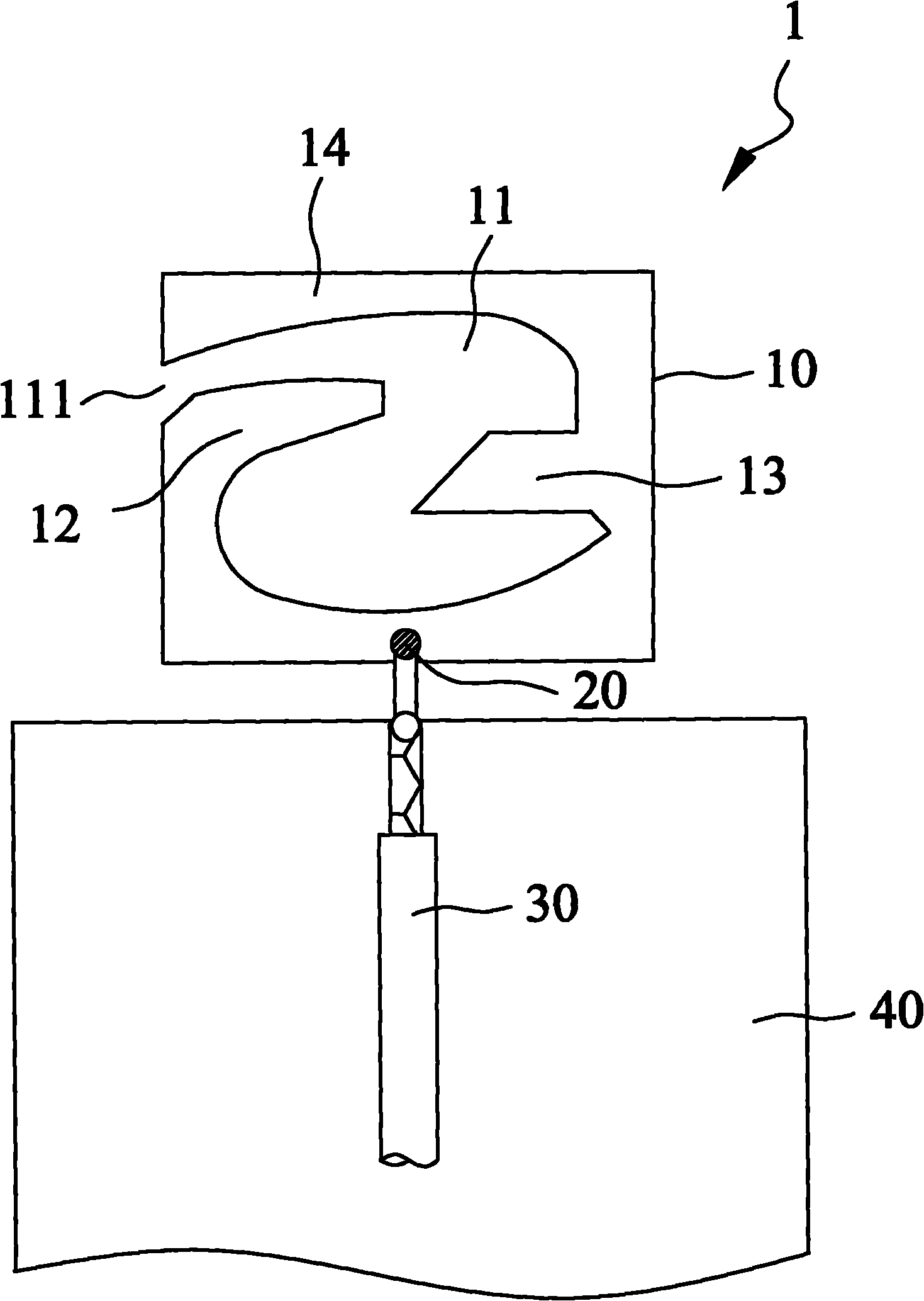
[0029] Please refer to the following figure 1 It is a structural schematic diagram of the first embodiment of the antenna module 1 of the present invention. The antenna module 1 of the present invention can be applied to electronic devices to transmit wireless signals. Such as figure 1 As shown, the antenna module 1 of the present invention includes an antenna body 10 and a feed-in point 20. The antenna body 10 is a rectangular metal sheet. The antenna body 10 forms a hollow part 11, and the hollow part 11 extends inward from one side of the antenna body 10. And the hollow portion 11 includes an opening 111 . The antenna body 10 can be divided into a first radiating portion 12 , a second radiating portion 13 and a third radiating portion 14 by the hollow portion 11 , and the opening 111 of the hollow portion...


PUM


Abstract

The invention relates to an electronic device and an antenna module thereof. Specifically, the antenna module is applied to the electronic device and used for transmitting wireless signals. The antenna module comprises an antenna body and a feed-in point, wherein the antenna body is a rectangular metal sheet; a hollow-out part is formed on the antenna body; the hollow-out part extends inwards from one side of the antenna body; the antenna body can be partitioned into a first radiation part, a second radiation part and a third radiation part by the hollow-out part; and the feed-in point is connected with the antenna body and is used for feeding in an electrical signal to the antenna body. Therefore, the first radiation part can form a first current path, the second radiation part can form a second current path, and the second radiation part is combined with the third radiation part to form a third current path, thereby generating different working frequency bands. The invention also has the functions of miniaturization and multi-frequency transmission supporting of the antenna module.

Description

technical field [0001] The invention relates to an antenna module applied to an electronic device, in particular to a multi-frequency antenna module capable of reducing volume and simplifying structural design and an electronic device thereof. Background technique [0002] With the vigorous development of wireless transmission technology, users can connect to the Internet at any time and place through portable electronic devices with wireless transmission functions, such as notebook computers, mobile phones or PDAs, which brings great convenience to people. sex. Generally, an antenna module is installed inside the portable electronic device, and a wireless transmission function is provided through the antenna module to send and receive signals. Since this type of portable electronic device is characterized by its portability, the structure is developed towards a thin, light and small design, so the antenna module must be designed to reduce its volume as much as possible; R...

Claims


Application Information

Patent Timeline
Patent Type & Authority Applications(China)
IPC IPC(8): H01Q1/36H01Q1/48H01Q1/22H01Q5/01H01Q9/04H01Q5/10
Inventor 孙榕成
Owner WISTRON CORP
Why Eureka
Try Eureka