
A speed measuring, positioning and triggering device for rail vehicle crash test

A crash test, rail vehicle technology, applied in the field of rail vehicle collision

Active Publication Date: 2021-12-14
CENT SOUTH UNIV
View PDF9 Cites 0 Cited by
  • Summary
  • Abstract
  • Description
  • Claims
  • Application Information

AI Technical Summary

Problems solved by technology

[0004] The purpose of the present invention is to provide a speed measuring, positioning and triggering device for rail vehicle crash test, so as to solve the technical defects existing in the prior art

Method used


Image

  • A speed measuring, positioning and triggering device for rail vehicle crash test
  • A speed measuring, positioning and triggering device for rail vehicle crash test
  • A speed measuring, positioning and triggering device for rail vehicle crash test

Examples


Embodiment Construction

[0023] The embodiments of the present invention will be described in detail below with reference to the accompanying drawings, but the present invention can be implemented in many different ways defined and covered by the claims.

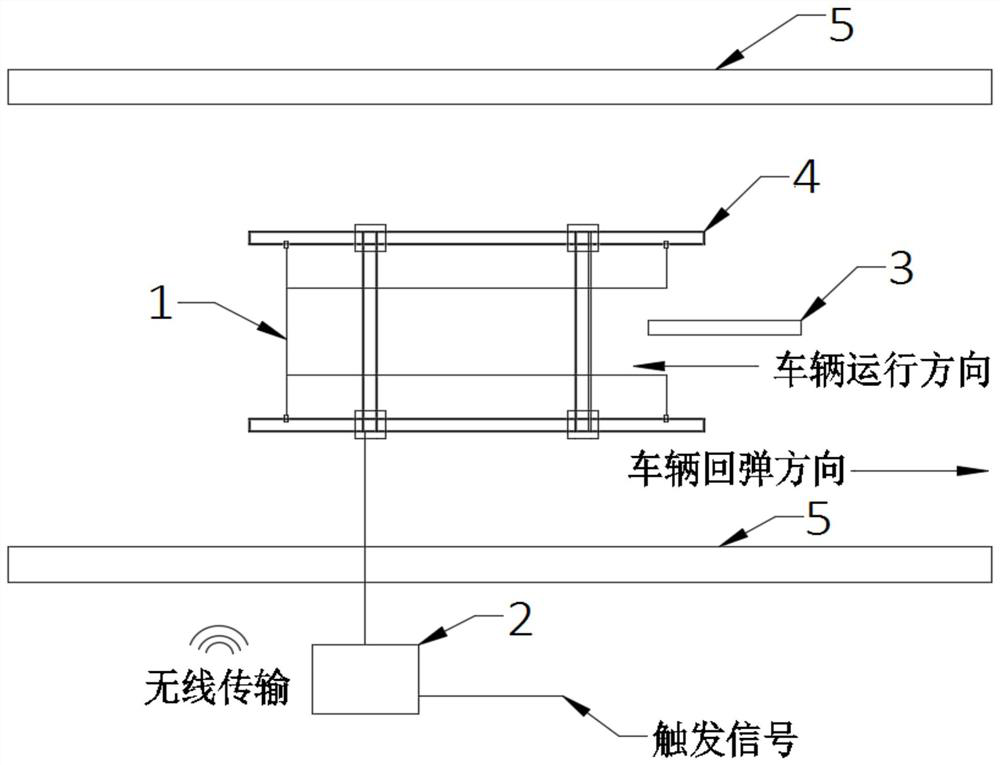
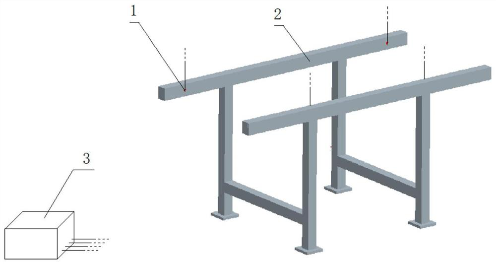
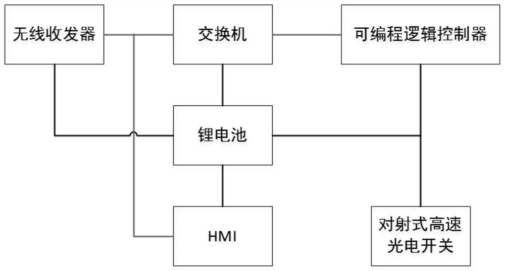
[0024] see figure 1 and figure 2 , the present invention provides a speed measuring, positioning and triggering device for a rail vehicle crash test, comprising two pairs of opposite beam high-speed photoelectric switches 1, a speed measuring box 2, a vehicle bottom mounting baffle 3 and a speed measuring frame 4, and the speed measuring frame 4 is placed between the two rails 5, and the opposite-beam high-speed photoelectric switch 1 is installed on the speed-measuring frame 4 and faces each other. The horizontal height of the two pairs of opposite-beam high-speed photoelectric switches 1 is the same and the lateral distance S, when the colliding vehicle passes by, and the baffle plate 3 installed at the bottom of the vehicle passes through the t...


PUM


Abstract

The invention provides a speed measuring, positioning and triggering device for a rail vehicle collision test, which includes two pairs of opposite beam high-speed photoelectric switches, a speed measuring box, a baffle and a speed measuring frame. The speed measuring frame is placed between two rails and has a height of Below the bottom of the colliding vehicle, the through-beam high-speed photoelectric switch is installed on the speed measuring frame and faces each other. The horizontal height of the two pairs of through-beam high-speed photoelectric switch is the same and the lateral distance is S. The baffle is installed at the bottom of the colliding vehicle. When the colliding vehicle passes through the through-beam high-speed photoelectric switch before and after the collision, the baffle blocks the through-beam ray so that the through-beam high-speed photoelectric switch generates an interruption signal and transmits the interruption signal to the speed measuring box electrically connected thereto. The device of the invention can realize the collision speed of the collision vehicle, the rebound speed monitoring after the collision, the position information feedback and the triggering of other test equipment at the same time. The device also has the characteristics of being portable, movable and self-powered, and has the function of wireless transmission.

Description

technical field [0001] The invention relates to the field of rail vehicle collisions, and specifically discloses a speed measuring, positioning and triggering device for rail vehicle collision tests. Background technique [0002] Rail vehicle collision accidents seriously threaten the safety of passengers. In order to reduce the losses caused by train collision accidents, it is necessary to study the crashworthiness of rail vehicle structures through real vehicle impact tests, and then develop impact-resistant and energy-absorbing car bodies to reduce losses caused by train collision accidents. In the real vehicle crash test of rail vehicles, it is necessary to monitor the collision speed of the collision vehicle and the rebound speed after the collision, monitor the positioning information of the collision vehicle when it passes the speed measurement point, and simultaneously trigger high-speed photography when the collision vehicle passes the speed measurement point and ot...

Claims


Application Information

Patent Timeline
Patent Type & Authority Patents(China)
IPC IPC(8): G01M17/08G01M7/08
CPCG01M17/08G01M7/08
Inventor 李田鲁寨军梁习锋许平彭勇周伟刘东润
Owner CENT SOUTH UNIV
Learn More