
Gas energy-saving recovery device

A technology of recovery device and gas, applied in glass manufacturing equipment, glass furnace equipment, glass production and other directions, can solve problems such as pollution of the environment and waste, and achieve the effect of good promotion and application prospects and significant emission reduction benefits.

Inactive Publication Date: 2010-08-18
山东省郓城县正达玻璃有限公司
View PDF4 Cites 0 Cited by
  • Summary
  • Abstract
  • Description
  • Claims
  • Application Information

AI Technical Summary

Problems solved by technology

[0002] The first kiln operated by our company is a 28m2 full gas, three-channel regenerative gas-fired horseshoe flame glass tank kiln. Since the direction is changed every 30 minutes, the interval between gas and air is 6-10 seconds each time. clock, causing a part of the gas in this interval to be discharged into the atmosphere from the chimney, which is wasted and pollutes the environment

Method used


Image

  • Gas energy-saving recovery device
  • Gas energy-saving recovery device
  • Gas energy-saving recovery device

Examples


Embodiment Construction

[0010] Accompanying drawing is a kind of specific embodiment of the present invention.

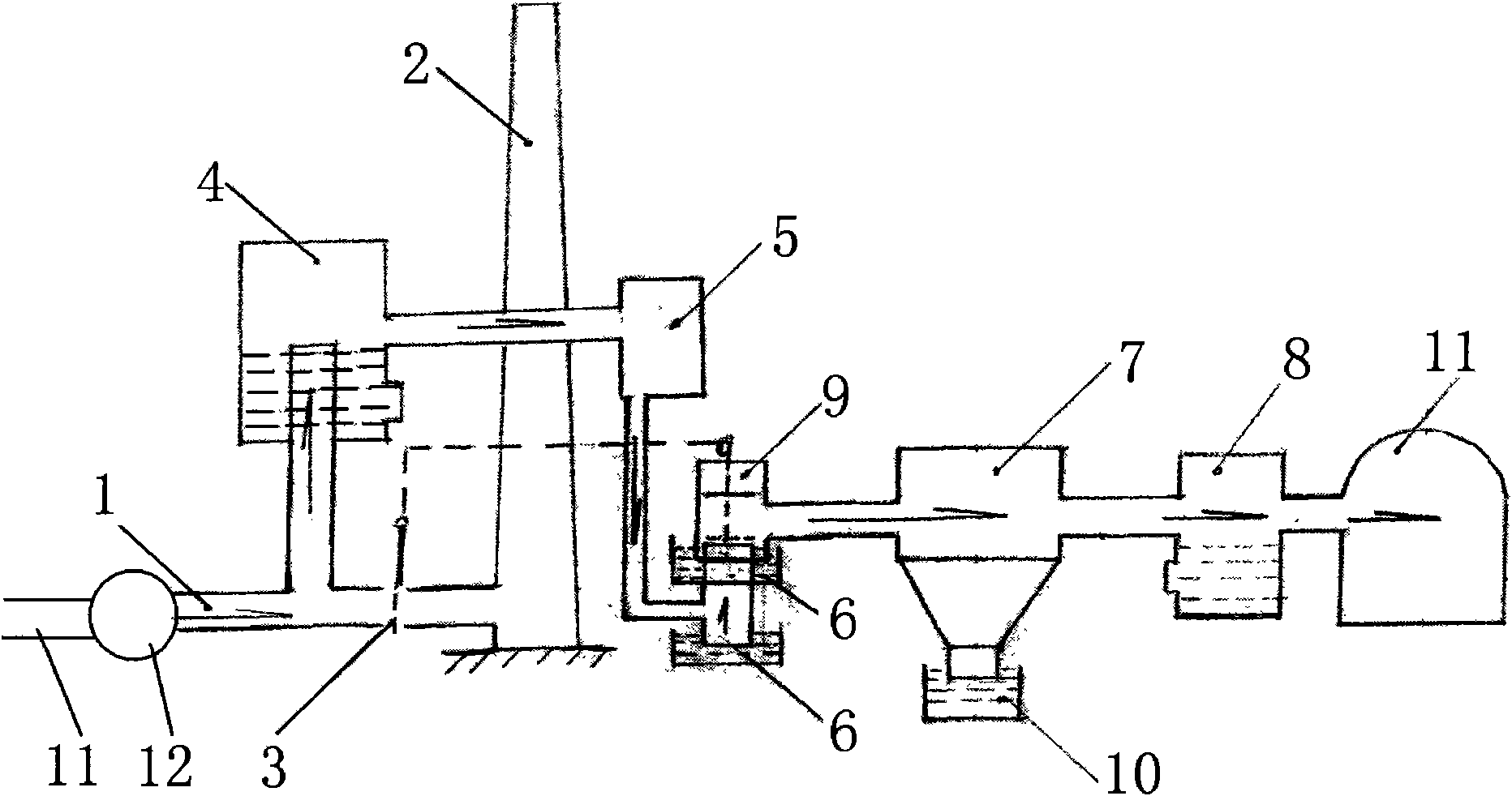
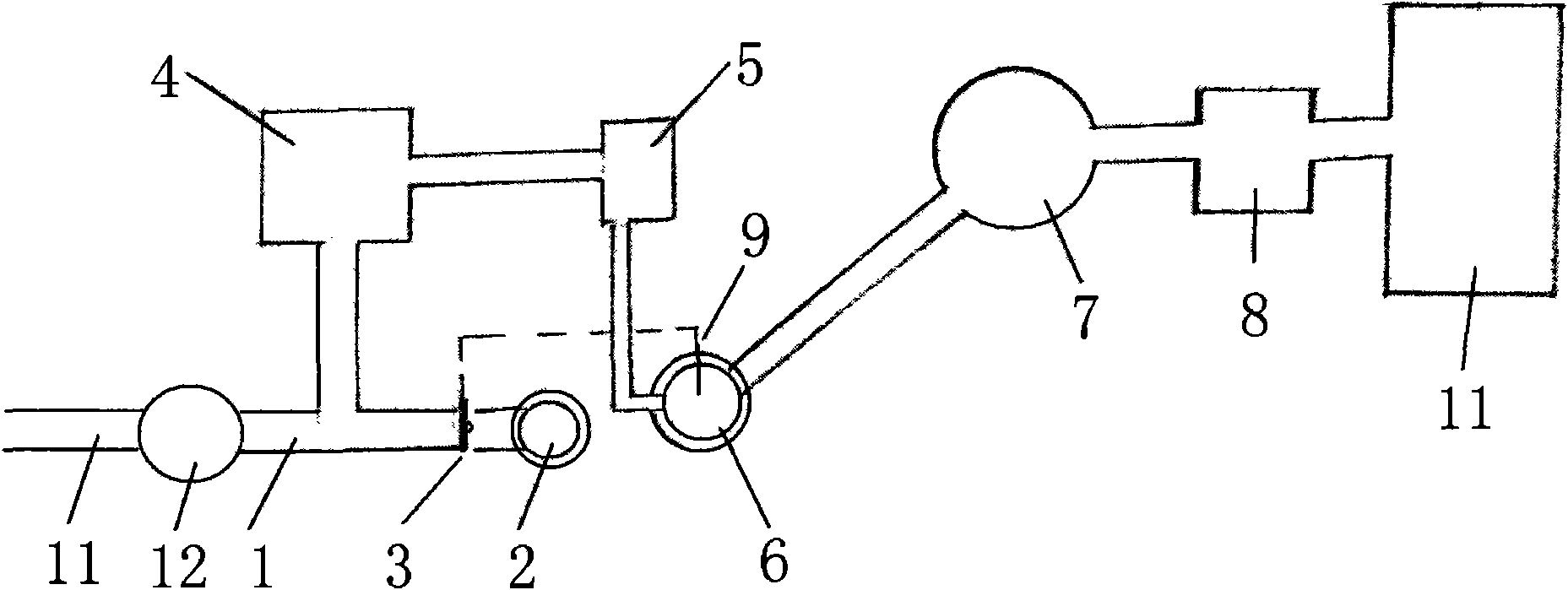
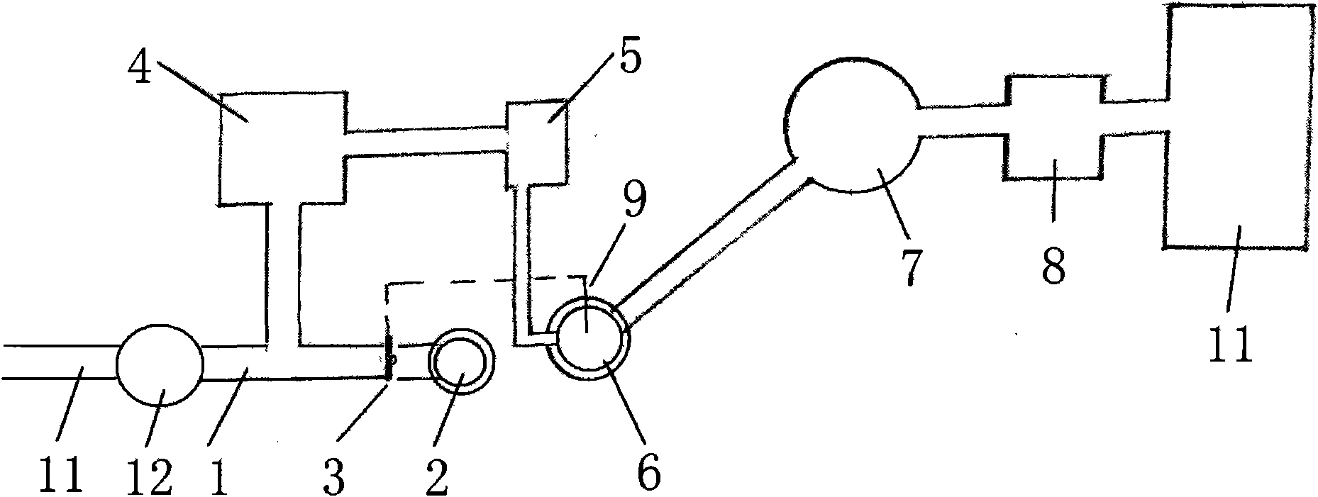
[0011] The gas energy-saving recovery device of the present invention includes a first gas flue 11, a gas exchanger 12, a second gas flue 1, and a chimney 2 connected in sequence, and a chimney inlet gate is set between the second gas flue 1 and the chimney 2 Plate 3, the second gas flue is connected to the first water sealing device 4, the induced draft fan 5, the second water sealing device 6, the gas storage tank 7, the third water sealing device 8 through pipelines before the chimney inlet gate, and the second The outlet of the third water sealing device is connected to the inlet of the first gas flue 11, the second water sealing device 6 is provided with a gas suction valve 9, and the bottom of the gas storage tank is provided with a fourth water sealing device 10. The size of the opening of the gas pipe and the chimney inlet valve plate is between 200X200mm and 2000X2000mm.

[0012]...


PUM


Abstract

The invention belongs to the field of combustion equipment, in particular to a gas energy-saving recovery device. The gas energy-saving recovery device comprises a first gas flue, a gas exchanger, a second gas flue, and a chimney which are connected in turn. A chimney inlet gate is arranged at the connecting position between the second gas flue and the chimney; and the second gas flue is positioned in front of the chimney inlet gate, and is connected with a first water seal device, a draught fan, a second water seal device, a gas holder, and a third water seal device in turn. The outlet of the third water seal device is connected with an inlet of the first gas flue; and a gas suction valve is arranged on the second water seal device. The gas energy-saving recovery device has the advantages of obvious effects of environmental protection, energy conservation and emission reduction, and recovers the gas lost in each commutation interval for re-burning in a furnace, wherein the coal saved per year is over hundreds of thousands of tons; and the device reduces the emission, is beneficial to the nation and the people, and has excellent popularization and application prospects.

Description

(1) Technical field [0001] The invention belongs to the field of combustion equipment, in particular to a gas energy-saving recovery device. (2) Background technology [0002] The first kiln operated by our company is a 28m2 full gas, three-channel regenerative gas-fired horseshoe flame glass tank kiln. Since the direction is changed every 30 minutes, the interval between gas and air is 6-10 seconds each time. clock, causing a part of the gas in this interval to be discharged into the atmosphere from the chimney, which is wasted and pollutes the environment. (3) Contents of the invention [0003] In order to make up for the deficiencies of the prior art, the invention provides a gas energy-saving recovery device with remarkable benefits of environmental protection, energy saving and emission reduction. [0004] The present invention is achieved through the following technical solutions: [0005] The gas energy-saving recovery device of the present invention includes a fi...

Claims


Application Information

Patent Timeline
Patent Type & Authority Applications(China)
IPC IPC(8): C03B5/16
CPCY02P40/50
Inventor 徐青山尹吉民李强何建功
Owner 山东省郓城县正达玻璃有限公司
Learn More