Wing plate for post-stall manipulation control of airplane
A wing plate and wing technology, applied in the aerospace field, can solve problems such as control surface failure, reduced control ability, insufficient aircraft stability, etc., to achieve control, increase instability and unsteadiness, and good conventional aerodynamics performance effect
- Summary
- Abstract
- Description
- Claims
- Application Information
AI Technical Summary
Problems solved by technology
Method used
Image
Examples
Embodiment 1
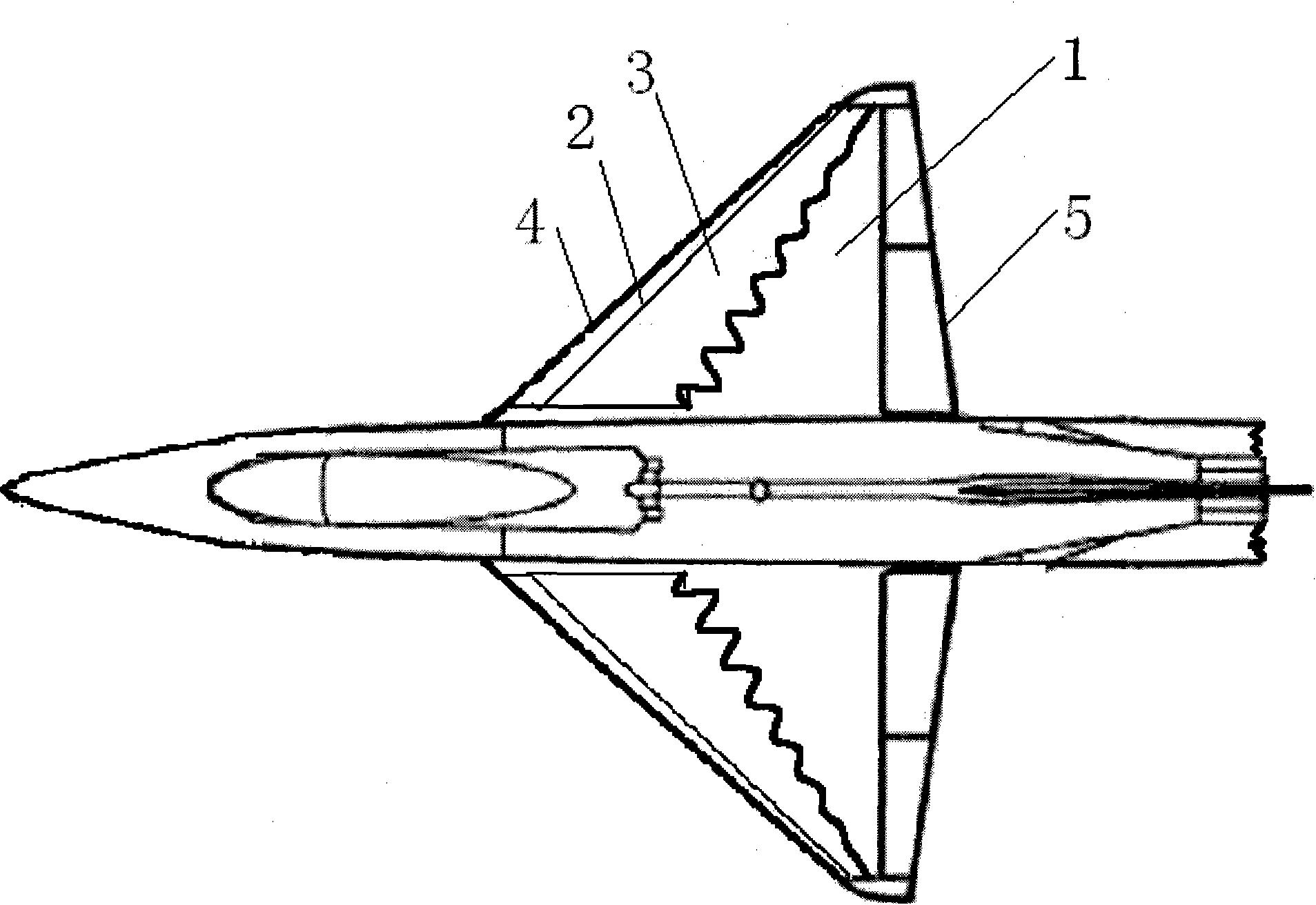
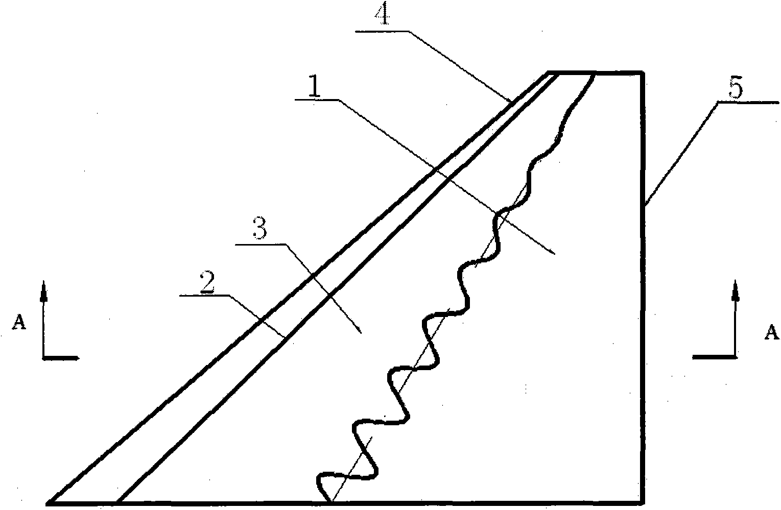
[0033] This embodiment is a wing plate used for the maneuvering control of the aircraft after a stall, including a wing 1 , a separation vortex control wing plate rotating shaft 2 and a separation vortex control wing plate 3 .
[0034]Wing 1 is trapezoidal, its root-chord ratio λ is 6; wing sweep angle α is 50°, wing span length b is 4390mm, root chord length C is 6282mm; wing airfoil is selected as NACA0006. Separate vortex control wing plates 3 are symmetrically installed on the upper surfaces of the wings 1 on both sides; this embodiment is described by taking one wing of an aircraft as an example.
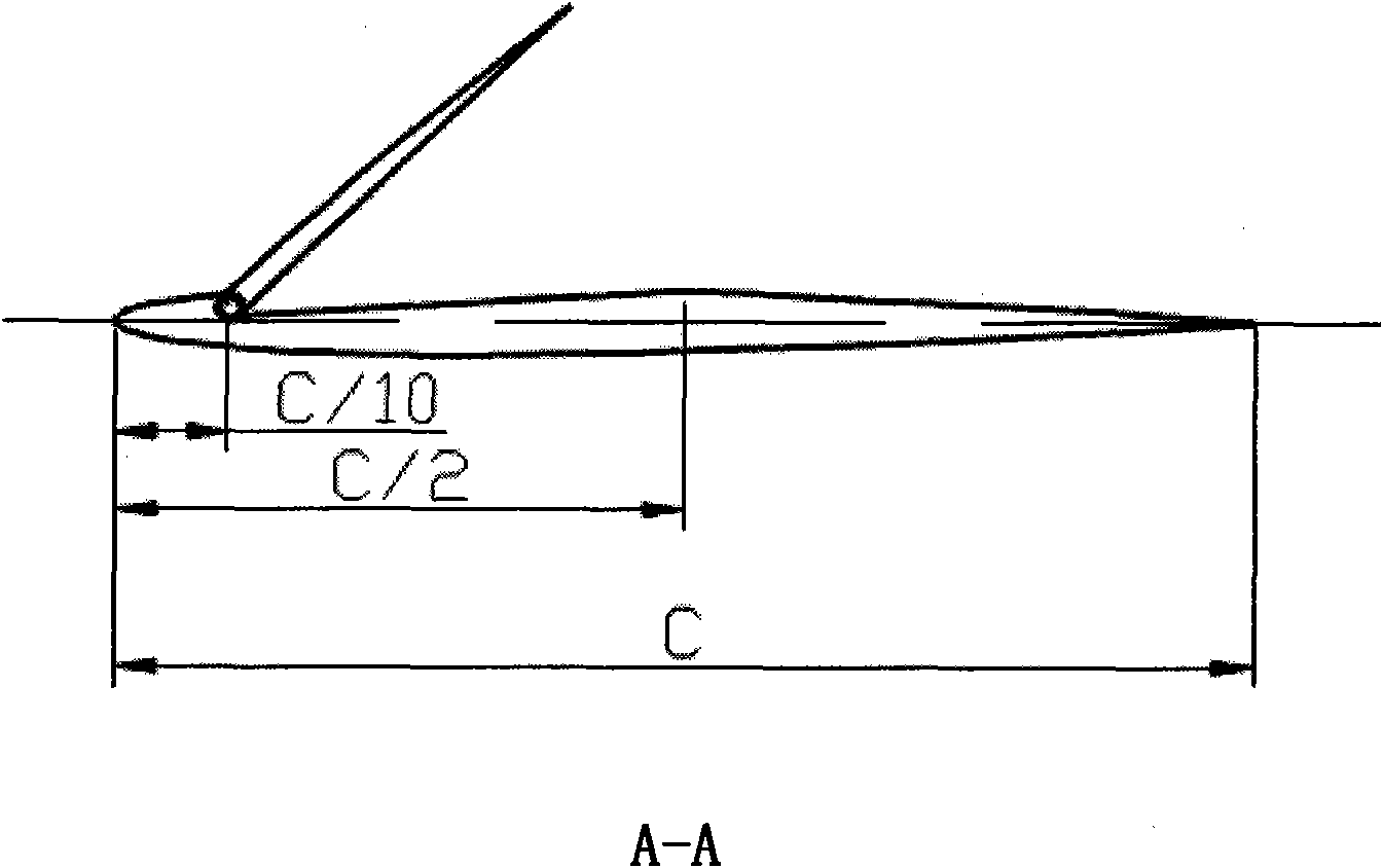
[0035] like image 3 shown. On the upper surface of the wings 1 on both sides, from the 10% chord length of the leading edge of the wing 1 to the 50% of the leading edge of the wing 1, there is a concave surface for the installation of the separation vortex control wing plate 3, and the concave surface is an inclined plane along the chord direction; The depth of the concave s...
Embodiment 2
[0047] The present embodiment is a wing plate used for aircraft post-stall maneuvering control, which is used for a light aircraft and includes a wing 1 , a separation vortex control wing plate rotating shaft 2 and a separation vortex control wing plate 3 .
[0048] Wing 1 is trapezoidal, its root-chord ratio λ is 5; wing sweep angle α is 45°, wing span length b is 3000mm, root chord length C is 3750mm; wing airfoil is selected as NACA0009. Separate vortex control wing plates 3 are symmetrically installed on the upper surfaces of the wings 1 on both sides; this embodiment is described by taking one wing of an aircraft as an example.
[0049] like image 3 shown. On the upper surface of the wings 1 on both sides, from the 10% chord length of the leading edge of the wing 1 to the 50% of the leading edge of the wing 1, there is a concave surface for the installation of the separation vortex control wing plate 3, and the concave surface is an inclined plane along the chord direct...
Embodiment 3
[0061] This embodiment is a wing plate used for the maneuvering control of the aircraft after a stall, including a wing 1 , a separation vortex control wing plate rotating shaft 2 and a separation vortex control wing plate 3 .
[0062] Wing 1 is trapezoidal, its root-chord ratio λ is 7; wing sweep angle α is 45°, wing span length b is 4500mm, root chord length C is 5250mm; wing airfoil is selected as NACA0012. Separate vortex control wing plates 3 are symmetrically installed on the upper surfaces of the wings 1 on both sides; this embodiment is described by taking one wing of an aircraft as an example.
[0063] like image 3 As shown, on the upper surface of the wings 1 on both sides, from the 10% chord length of the leading edge of the wing 1 to the 50% of the leading edge of the wing 1, there is a concave surface for the installation of the separation vortex control wing plate 3, and the concave surface is along the chord direction. Inclined surface: The depth of the concav...
PUM
 Abstract
Description
Claims
Application Information
 - R&D
- Intellectual Property
- Life Sciences
- Materials
- Tech Scout
- Unparalleled Data Quality
- Higher Quality Content
- 60% Fewer Hallucinations
Browse by: Latest US Patents, China's latest patents, Technical Efficacy Thesaurus, Application Domain, Technology Topic, Popular Technical Reports.
© 2025 PatSnap. All rights reserved.Legal|Privacy policy|Modern Slavery Act Transparency Statement|Sitemap|About US| Contact US: help@patsnap.com


