A Pneumatic Needle-Free Injector Power Head

A technology of needle-free injector and power head, which is applied in the field of medical devices and can solve the problems of high injection cost, complex structure of spring-type needle-free injector, high-pressure gas leakage, etc.

Active Publication Date: 2011-12-07
扬中市检验检测中心
View PDF0 Cites 0 Cited by
  • Summary
  • Abstract
  • Description
  • Claims
  • Application Information

AI Technical Summary

Problems solved by technology

Due to the complex structure of the spring-type needle-free syringe, the high price, and the large force of the reset operation, it is not generally accepted by the market; the needle-free syringe with detonation air pressure as the power source needs temporary impact ignition, which will generate high temperature and affect Therefore, it is also difficult to popularize; although the pneumatic needle-free syringe packaged with air pressure as the power source has a simple structure and a low price, it can be accepted by the public, but there is a technical problem in product development at present, that is, the needle-free syringe is still in storage. The high-pressure gas will leak slowly during the discharge process, and it is difficult to store the product for a long time, and the needle-free syringe packaged with air pressure as the power source can only be used once, and the cost of each injection for consumers is relatively high; Needle-free syringes can be stored for a long time and the power head of the syringe itself can be used repeatedly, which is what manufacturers and consumers want

Method used


Image

  • A Pneumatic Needle-Free Injector Power Head
  • A Pneumatic Needle-Free Injector Power Head

Examples


Embodiment Construction

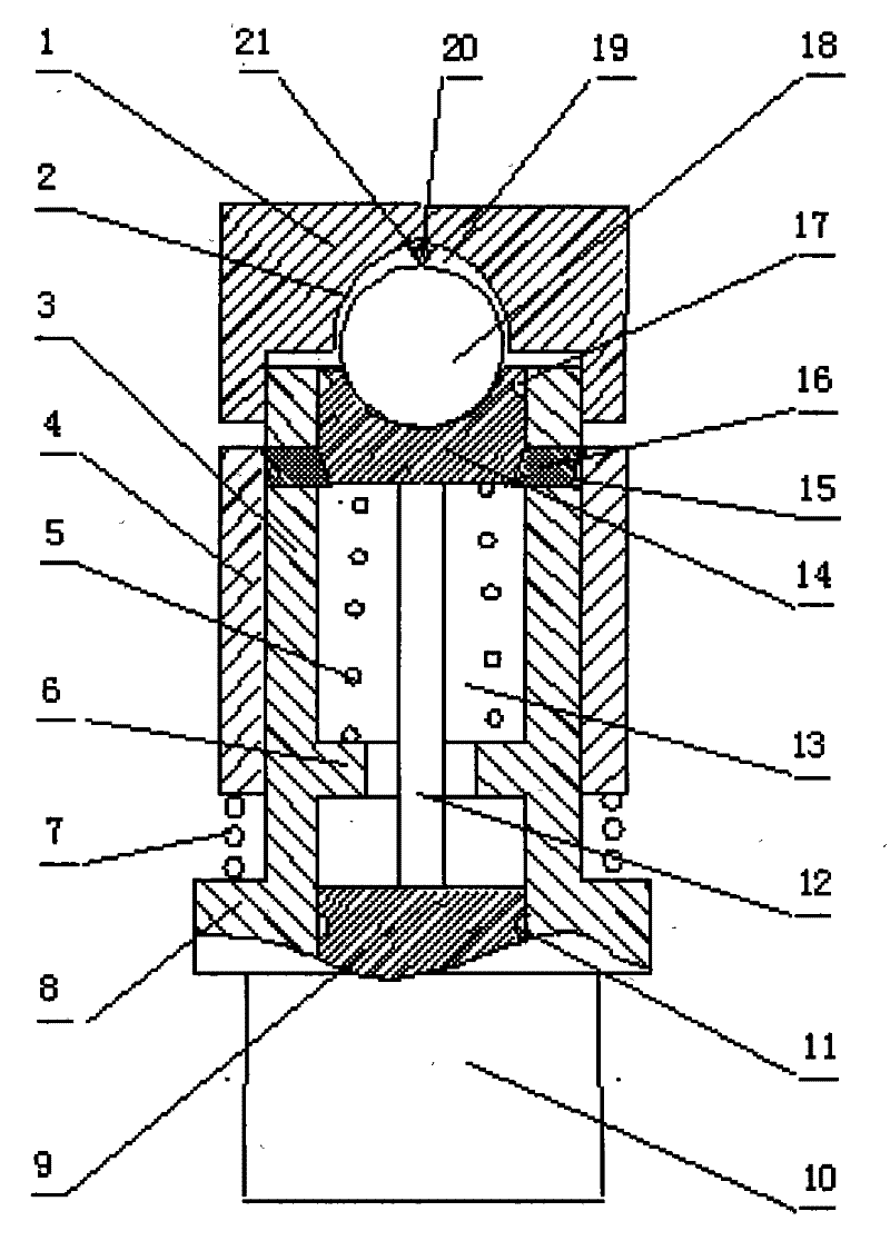
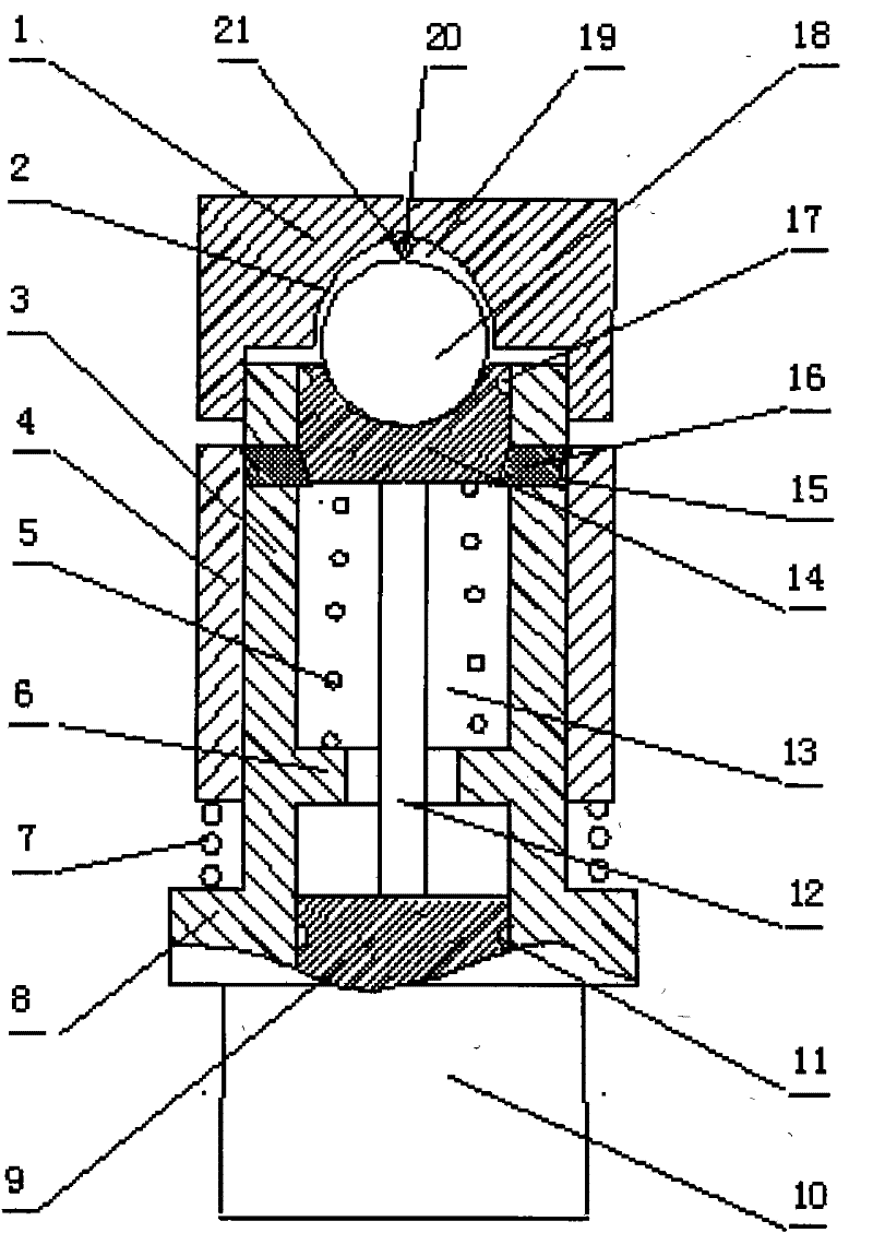
[0007] figure 1 1 is the cap, 2 is the inner arc surface, 3 is the cylinder, 4 is the sliding sleeve, 5 is the piston return spring, 6 is the inner shoulder of the cylinder, 7 is the sliding sleeve spring, 8 is the outer shoulder of the cylinder, 9 is the lower Piston block, 10 is the drug injection head, 11 is the lower sealing ring, 12 is the connecting rod, 13 is the inner hole of the cylinder, 14 is the upper piston block, 15 is the stop pin hole, 16 is the movable stop pin, 17 is the upper seal ring, 18 is a metal thin-walled ball, 19 is a cavity, 20 is a slotted point drill, and 21 is a groove. The cylinder 3 has a cylinder hole 13 with through holes up and down. The upper part of the cylinder 3 is sealed and screwed with the cap 1. The lower part of the cap 1 has an inner arc surface 2 and the top arc of the inner arc surface 2 There is a slotted tip drill 20 fixed on the cap 1, with a slot 21 on the slotted tip drill 20, and the tip of the slotted tip drill 20 is downw...


PUM


Abstract

A pneumatic needle-free injector power head, which includes a barrel, the upper part of the barrel is sealed and screwed into a cap, the lower part of the barrel is connected to a drug injection head, and a piston assembly with a reset device is installed in the inner hole of the barrel. A movable stop pin for controlling the downward movement of the plug is installed, and a sliding sleeve for controlling the movable stop pin is installed outside the cylinder, and the sliding sleeve is connected with a return spring. The small wall ball is placed in the cavity between the top of the piston assembly in the inner hole of the cylinder and the cap, and there is a slotted pointed drill fixed in the cap above the thin metal ball. This power head enables long-term storage of pneumatic needle-free syringes.

Description

Technical field [0001] The invention belongs to the technical field of medical devices, and in particular relates to a pneumatic needleless injector power head. Background technique [0002] At present, there are basically two types of power sources for needleless syringes. One type uses a powerful spring as a power source. We call it a spring-type needleless syringe. The other type uses air pressure as a power source, including detonating air pressure and packaging. Air pressure, the latter we call it a pneumatic needleless syringe. Due to the complex structure of the spring-type needle-free syringe, the high price, and the large force during the reset operation, it is not generally accepted by the market; the needle-free syringe with the detonating air pressure as the power source needs temporary impact and ignition, which will produce high temperature and affect It is also difficult to promote its efficacy; although the pneumatic needleless syringe with encapsulated air press...

Claims


Application Information

Patent Timeline
Patent Type & Authority Patents(China)
IPC IPC(8): A61M5/303
Inventor 傅雅芬
Owner 扬中市检验检测中心
Why Eureka
Try Eureka