
Machine recognition method and device between imaging device and imaging box

An imaging device and imaging box technology, which is applied in the fields of electrography, optics, instruments, etc., can solve the problems of low versatility and high cycle time of imaging box chips, and achieve the goal of shortening the development cycle, reducing development costs, and expanding the scope of use Effect

Active Publication Date: 2010-08-04
APEX MICROELECTRONICS CO LTD
View PDF4 Cites 17 Cited by
  • Summary
  • Abstract
  • Description
  • Claims
  • Application Information

AI Technical Summary

Problems solved by technology

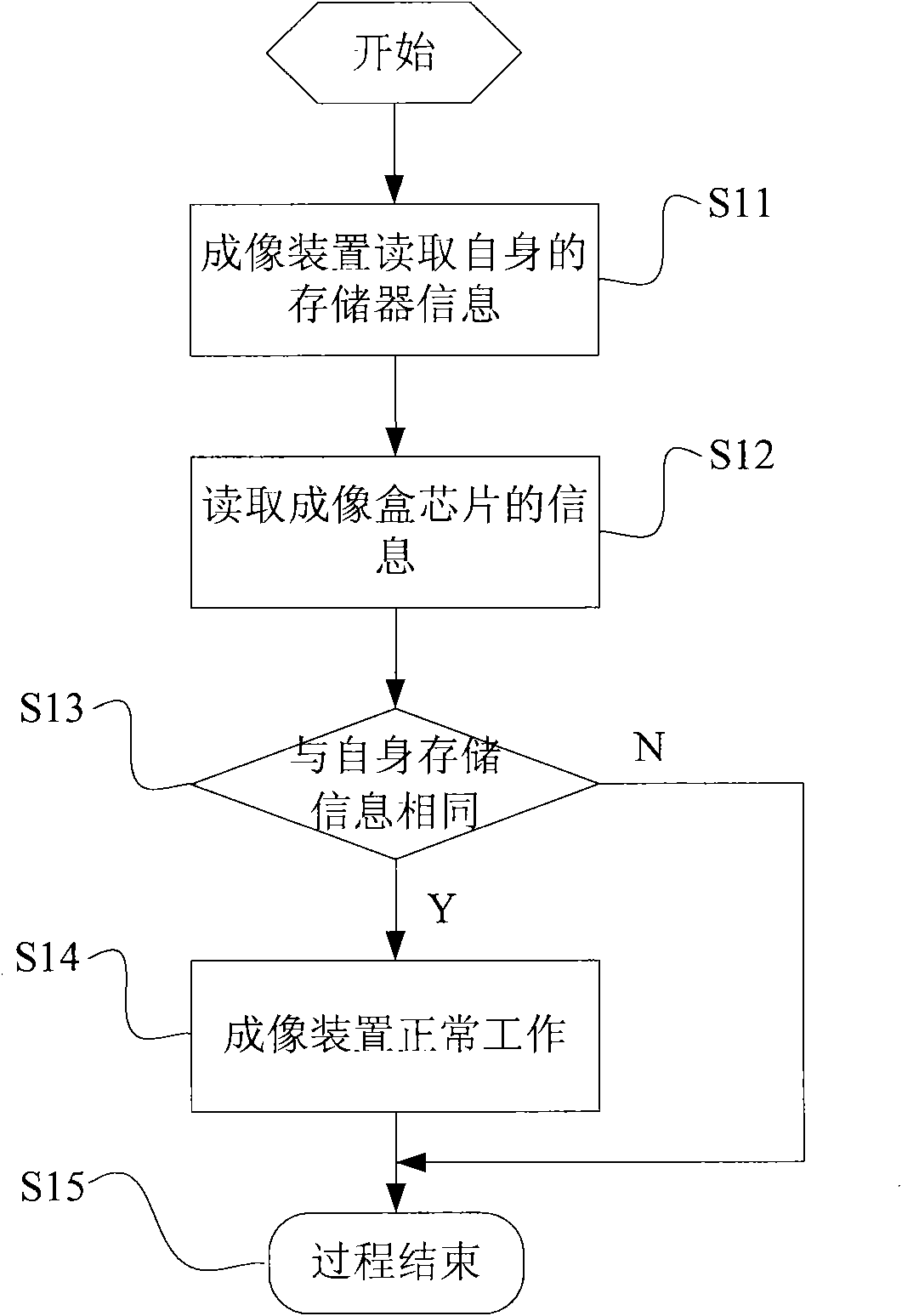
[0013] In view of this, the present invention provides a recognition method and device between an imaging device and an imaging box to solve the problems of low versatility, development cost, and long cycle time of imaging box chips in the prior art

Method used

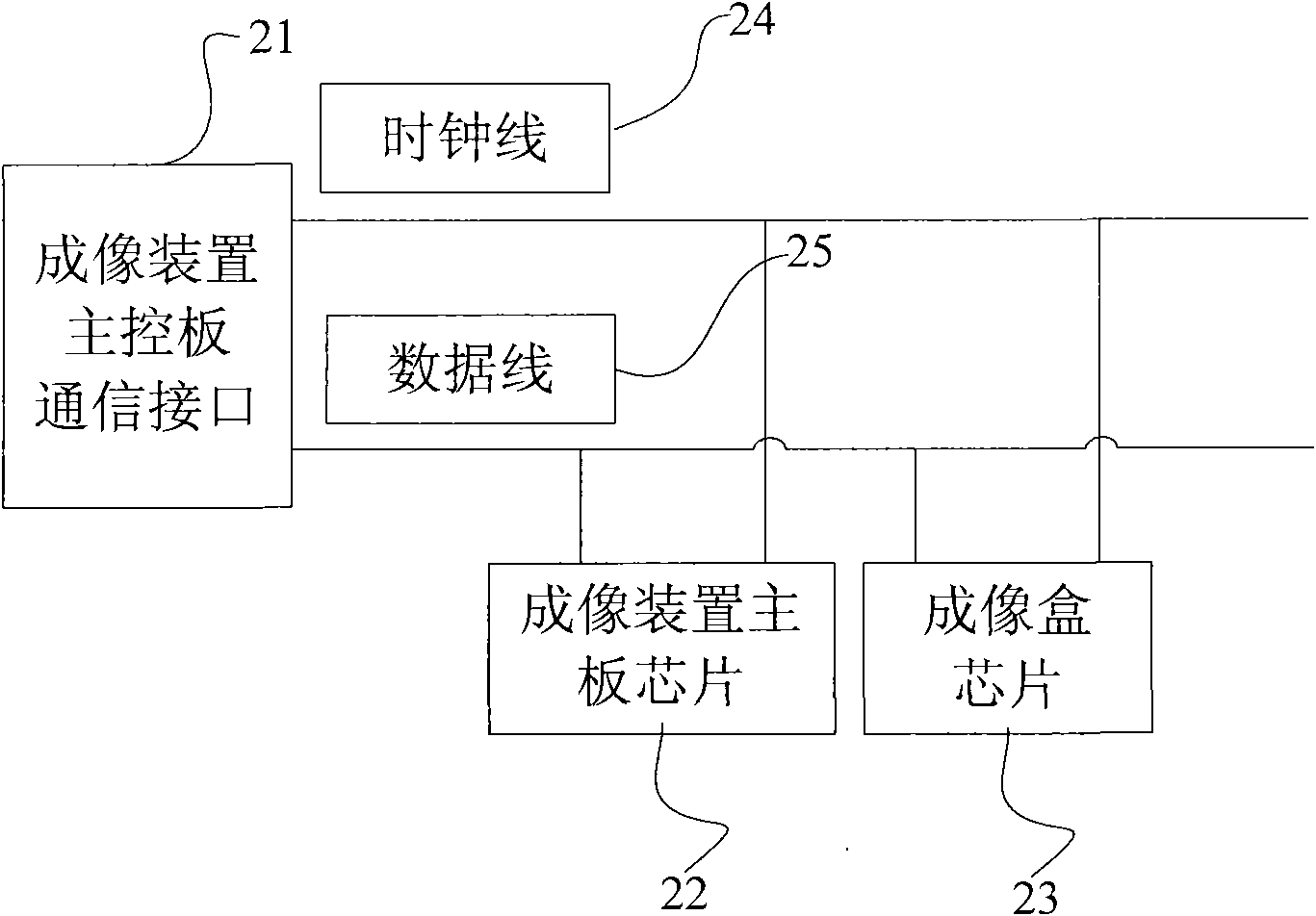

Image

  • Machine recognition method and device between imaging device and imaging box
  • Machine recognition method and device between imaging device and imaging box
  • Machine recognition method and device between imaging device and imaging box

Examples


Embodiment 1

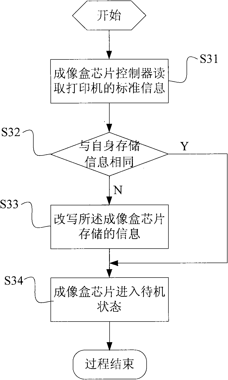
[0052] Embodiment 1 of the present invention takes a printer as an example, and discloses a process flow of a recognition method between a printer and an imaging box as follows: image 3 shown, including:

[0053] Step S31, the chip controller of the imaging box reads the standard information of the printer;

[0054] Step S32, comparing the standard information to be read by the controller with the information stored in the imaging cartridge chip, when the comparison result is the same, execute step S34, if not, execute step S33;

[0055]Step S33, the controller rewrites the information stored in the imaging cartridge chip according to the read standard information;

[0056] Step S34 , the chip of the imaging cartridge enters a standby state, waiting to receive tasks from the printer.

[0057] In addition to the above operations, the following steps can also be added after step S33:

[0058] Step a, the controller reads the information stored in the rewritten imaging cartri...

Embodiment 2

[0064] This implementation takes the powder box chip controller as an example to further describe the flow of the machine recognition method between the printer and the imaging box. The flow is as follows Figure 5 shown, including:

[0065] Step S51, initializing the powder container chip controller;

[0066] Step S52, judging whether the bus is idle, if the bus is busy, then execute step S53, if the bus is idle, then continue to execute step S54;

[0067] Step S53, delaying the preset time, and continuing to judge the bus state;

[0068] Step S54, the toner box controller reads the standard information stored in the printer;

[0069] Step S55, compare the standard information read by the controller with the information stored in the powder container chip, when the comparison result is the same, execute step S512, if not, execute step S56;

[0070] Step S56, the controller rewrites the information stored in the powder container chip according to the read standard informati...


PUM


Abstract

The invention discloses a machine recognition method between an imaging device and an imaging box. The method comprises the following steps of: reading the standard information of the imaging device; comparing the read standard information with the information stored in an imaging box chip; when the read standard information is different from the information stored in the imaging box chip, rewriting the information stored in the imaging box chip by using a controller according to the read standard information; and updating the state of the imaging box chip into a standby state and waiting for receiving a task of the imaging device. In the machine recognition process between the imaging device and the imaging box, the standard information of a printer is read by the imaging box chip and the information stored in the imaging box chip is rewritten according to the standard information so as to make the imaging box chip applied to the imaging devices requiring different matching information, therefore, the method and the device enlarge the application range of the chip, enhance the universality of the chip, accelerate the machine recognition process, change the conventional chip development process, shorten the chip development period and reduce the development cost.

Description

technical field [0001] The invention relates to the field of office equipment, in particular to a machine recognition method and device between an imaging device and an imaging box. Background technique [0002] Existing imaging devices, such as printers, copiers and fax machines, will be used in conjunction with imaging boxes. The chips of existing imaging boxes generally include information such as the manufacturer’s logo, capacity, area, and serial number of the imaging device, while the imaging device’s The memory of the motherboard also records the standard information of the imaging device, which also includes information such as the manufacturer's logo, capacity, area, and serial number of the imaging device. These information are used to measure whether the chip information of the imaging box is correct. [0003] The most important step in the development process of the existing imaging box chip is the recognition process between the imaging device imaging device and...

Claims


Application Information

Patent Timeline
IPC IPC(8): G03G21/18
Inventor 宋丰君
Owner APEX MICROELECTRONICS CO LTD
Learn More