
Equipment and method for measuring decoupling factor of optical fiber gyro

A technology of decoupling coefficient and testing optical fiber, applied in measurement devices, instruments, etc., can solve the problems of inability to measure the instantaneous decoupling accuracy of the fiber optic gyroscope, poor measurement accuracy, etc.

Inactive Publication Date: 2010-08-04
湖南振华领创科技有限公司
View PDF0 Cites 8 Cited by
  • Summary
  • Abstract
  • Description
  • Claims
  • Application Information

AI Technical Summary

Problems solved by technology

The traditional method of measuring the decoupling coefficient of the fiber optic gyroscope has poor measurement accuracy. It is a static approximate measurement method and cannot measure the instantaneous decoupling accuracy of the fiber optic gyroscope during its operation.

Method used


Image

  • Equipment and method for measuring decoupling factor of optical fiber gyro
  • Equipment and method for measuring decoupling factor of optical fiber gyro
  • Equipment and method for measuring decoupling factor of optical fiber gyro

Examples


Embodiment Construction

[0053] In order to make the technical means, creative features, goals and effects achieved by the present invention easy to understand, the present invention will be further described below in conjunction with specific illustrations.

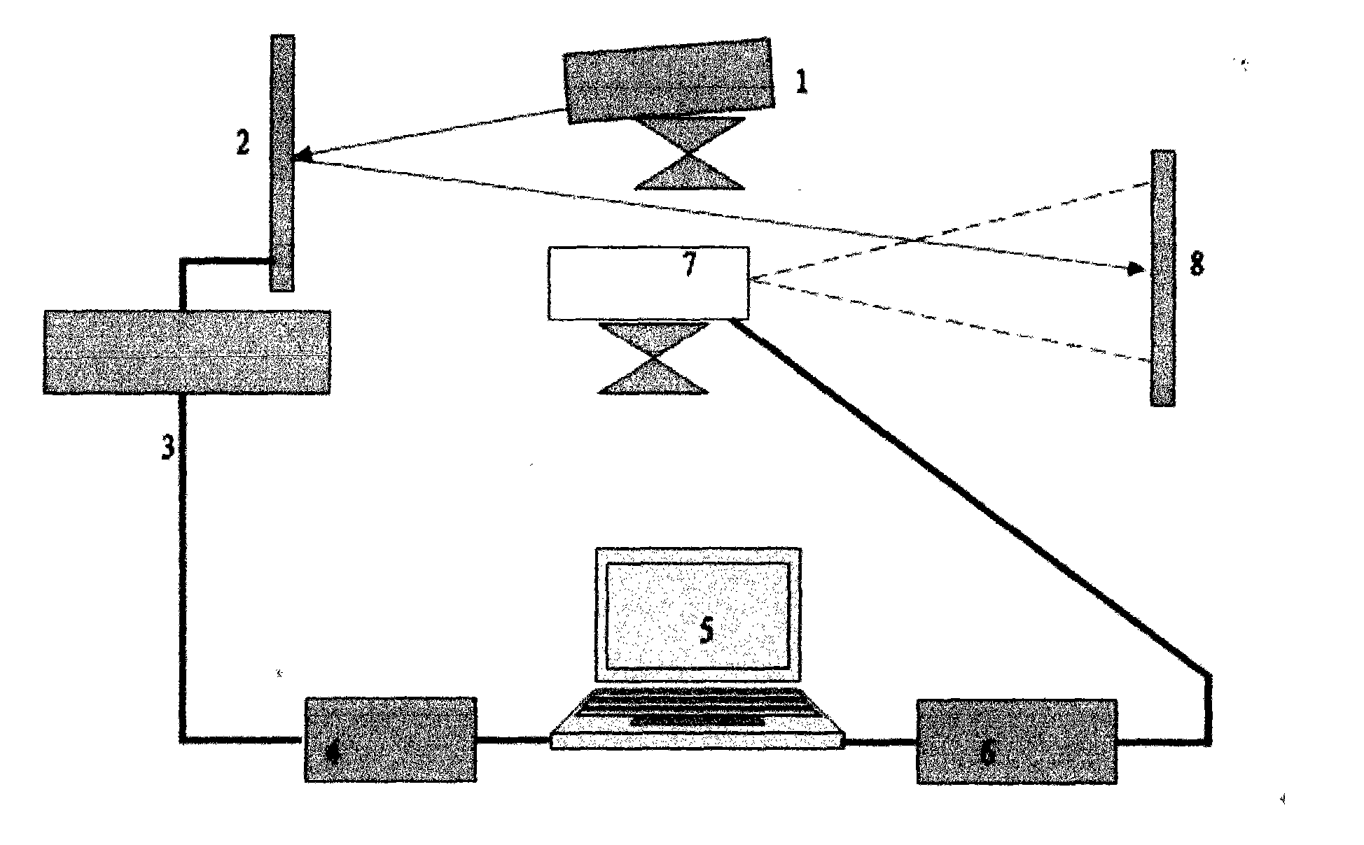
[0054] A device for testing the decoupling coefficient of a fiber optic gyroscope, comprising: a laser 1, a test device 2, a turntable motion acquisition card 3, a 485 interface 4, a data analysis system 5, an image acquisition card 6, a high-speed camera 7, and a projection screen 8. The test device 2 is connected to the turntable motion acquisition card 3, the turntable motion acquisition card 3 is connected to the 485 interface 4, the 485 interface 4 is connected to the data analysis system 5, the data analysis system 5 is connected to the image acquisition card 6, and the image acquisition card 6 is connected to the high-speed camera 7.

[0055] Put the fiber optic gyroscope under test into the test device 2, the laser light emitted by the la...


PUM


Abstract

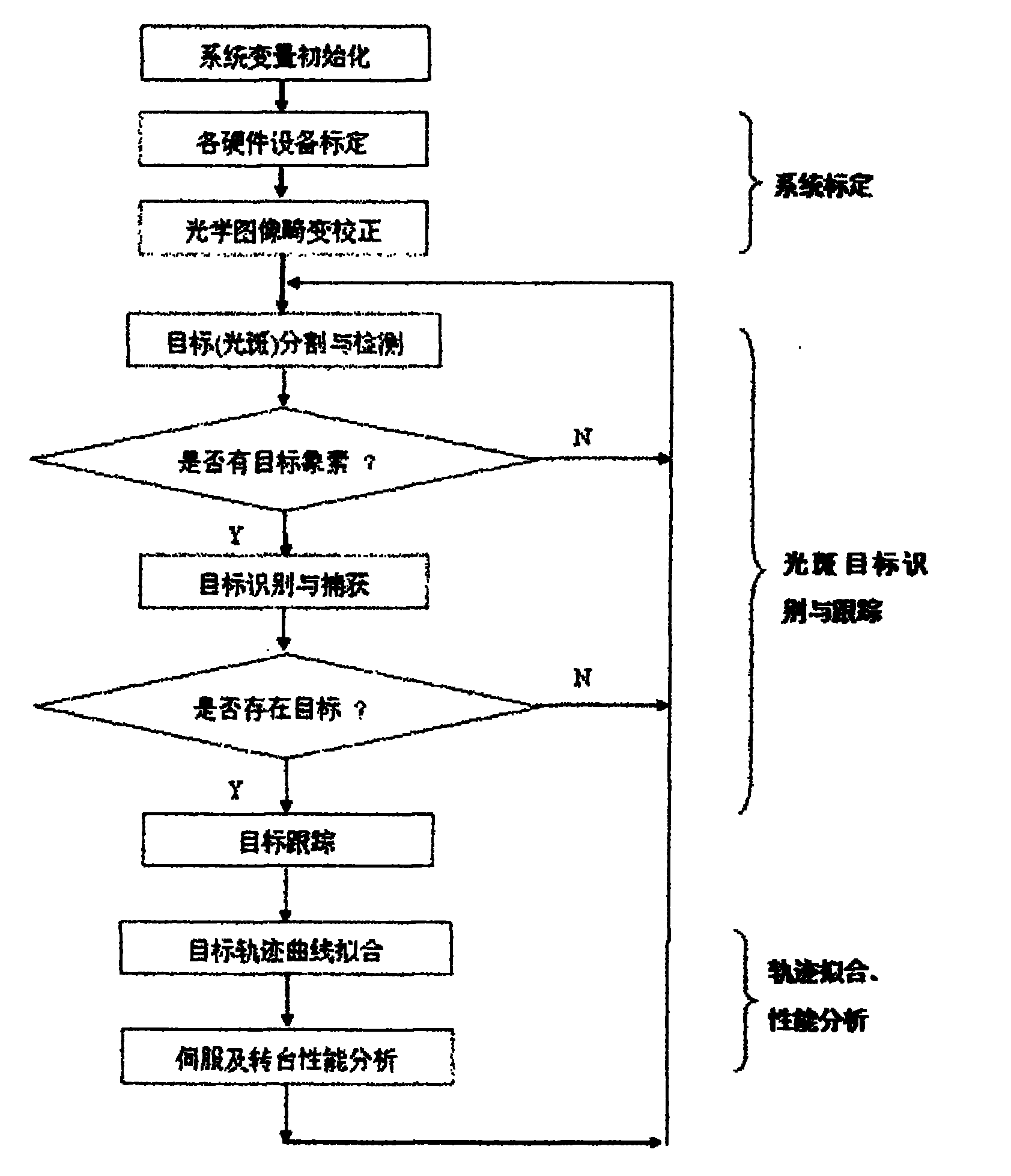
The invention provides equipment and a method for measuring a decoupling factor of an optical fiber gyro. The measuring equipment comprises a laser, a measuring device, a rotary platform moving acquisition card, a 485 interface, a data analysis system, an image acquisition card, a high-speed camera and a projection screen. The measuring method comprises the following steps that: based on the fact that laser emitted by the laser is reflected when projected onto the equipment to be measured and the fact that the reflected light forms a tiny round spot on the screen, the high-speed camera acquires the moving track image of the round spot on the screen in real time and sends the image to the data analysis system of a computer; and when the equipment to be measured moves along an azimuth axis and a pitch axis, the light spot forms the moving track, corresponding to moving parameters and a moving precision of the equipment to be measured, on the screen, by dividing, identifying and tracking the light spot of the acquired high-speed image sequence, the data analysis system of the computer fits the moving curve of the round spot in the time direction, and calculates moving information based on the fitting curve. The equipment has the advantages of being easily and conveniently operated and effectively overcoming defects existing in the conventional method.

Description

technical field [0001] The invention relates to equipment and a dynamic testing method for testing the decoupling coefficient of an optical fiber gyroscope, in particular to a device and a testing method for testing the decoupling coefficient of an optical fiber gyroscope through high-speed image acquisition, image moving target recognition, and target tracking. Background technique [0002] The fiber optic gyroscope is a core device of an inertial navigation system, which determines the working accuracy of the inertial system. With the advancement of science and technology, fiber optic gyroscopes with low cost, small size and low power consumption have been widely used in the guidance systems of micro-systems and tactical weapons, and are important low-precision angular velocity sensors. [0003] The traditional method is to use a scale to manually measure the displacement of the fiber optic gyroscope before and after the closed loop. The decoupling accuracy is equal to the...

Claims


Application Information

Patent Timeline
IPC IPC(8): G01C25/00
Inventor 鲁新平李吉成王成春李剑武罗宇谦余知音张理明
Owner 湖南振华领创科技有限公司
Learn More