
Three-dimensional multidirectional-sensitive micromechanical inertial electrical switch

A micro-mechanical, multi-directional technology, applied in electrical switches, circuits, electrical components, etc., can solve problems such as short time, poor contact effect, and high stiffness

Inactive Publication Date: 2010-07-28
SHANGHAI JIAO TONG UNIV
View PDF4 Cites 22 Cited by
  • Summary
  • Abstract
  • Description
  • Claims
  • Application Information

AI Technical Summary

Problems solved by technology

For horizontally driven inertial electrical switches, since the mass block cannot be plated too thick on the silicon substrate, the mass block needs to occupy a large area to generate a large enough inertial driving force to trigger the switch, and the inertial switch has no obvious three-dimensional structure; For the vertically driven inertial switch, when the electrode of the mass block collides with another electrode directly on the substrate, the rigidity of both is very large, so that the contact effect is poor and the time is short, coupled with the mass of high-speed rebound block does not have any boundary guards and may result in device damage
More importantly, none of the switching devices proposed in the paper can be used independently to simultaneously detect acceleration shocks in multiple directions

Method used


Image

  • Three-dimensional multidirectional-sensitive micromechanical inertial electrical switch
  • Three-dimensional multidirectional-sensitive micromechanical inertial electrical switch
  • Three-dimensional multidirectional-sensitive micromechanical inertial electrical switch

Examples


Embodiment 1

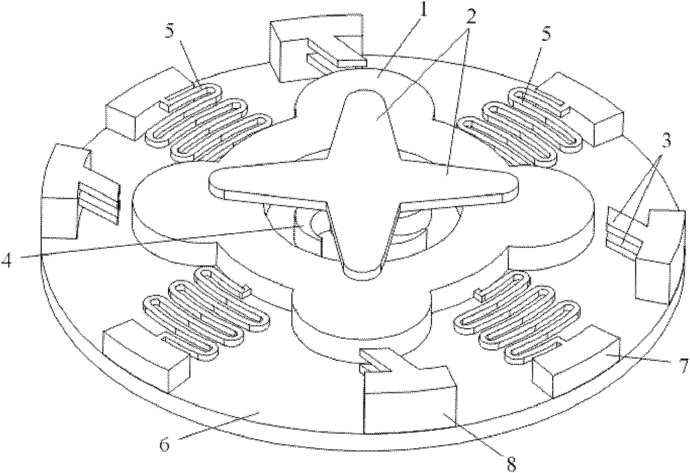
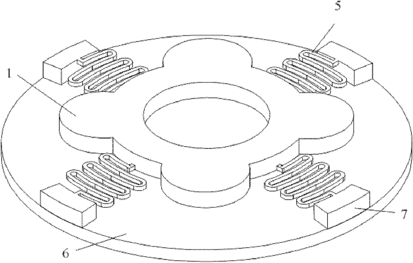
[0028] Such as figure 1 As shown, this embodiment includes: mass electrode 1, cantilever beam vertical fixed electrode 2, cantilever beam horizontal fixed electrode 3, spiral horizontal fixed electrode 4, serpentine spring 5, insulating substrate 6, spring support seat 7, cantilever Beam supporting base 8, spiral fixed electrode supporting base 9 and vertical fixed electrode supporting base 10, wherein: mass electrode 1 is connected with one end of four sets of serpentine springs 5 ​​respectively, and the other ends of four sets of serpentine springs 5 ​​are connected with the spring supporting base 7 phases are connected and the mass electrode 1 is suspended above the insulating substrate 6 and 10 to 50 microns below the cantilever beam vertical fixed electrode 2, and the spring support seat 7 and the cantilever beam support seat 8 are respectively fixed on the insulating substrate 6 and Located around the mass electrode 1, the distance between the cantilever beam support bas...

Embodiment 2

[0044] Such as Figure 5 As shown, in this embodiment, the horizontal fixed electrode 3 of the cantilever beam with a single-layer structure is arranged on the periphery of the mass electrode 1. The three-dimensional multi-directional sensitive micromechanical inertial electrical switch is the same, and except for the fixed electrode of the horizontal cantilever beam, the shape and size of the other components are the same as those in Embodiment 1.

Embodiment 3

[0046] Such as Figure 6 As shown, in this embodiment, a cantilever beam with a cylindrical plane with holes is used to vertically fix the electrode 2. The radius of the cylindrical plane of the vertical fixed electrode 2 is 500-1000 microns, and the thickness is 20-50 microns. The through hole 11 has a radius of 10 to 50 microns, uniformly distributed on the cylinder, the distribution pitch is 50 to 100 microns, and the rest of the features of the micromechanical inertial electrical switch are similar to those of Embodiment 1.


PUM

PropertyMeasurementUnit
Outer diameteraaaaaaaaaa
The inside diameter ofaaaaaaaaaa
Widthaaaaaaaaaa

Abstract

The invention discloses a three-dimensional multidirectional-sensitive micromechanical inertial electrical switch in the technical field of micromechanical systems. The switch comprises a mass block electrode, a horizontal cantilever beam fixing electrode, a spiral horizontal fixing electrode, a vertical cantilever beam fixing electrode, a plurality of groups of serpentine springs, an insulating substrate, a spiral fixing electrode support seat, a spring support seat, a vertical fixing electrode support seat and a cantilever beam support seat, wherein the mass block electrode is connected with one end of each of four groups of serpentine springs respectively, the other end of the serpentine spring is connected with the spring support seat and suspends the mass block electrode between the insulating substrate and the vertical cantilever beam fixing electrode, the spring support seat and the cantilever beam support seat are fixedly arranged on the insulating substrate respectively and positioned around the mass block electrode, and the spiral horizontal fixing electrode and the spiral fixing electrode support seat are fixedly arranged on the substrate in turn. The micromechanical inertial electrical switch is sensitive to the acceleration shock in horizontal and vertical multiple directions.

Description

technical field [0001] The invention relates to a device in the technical field of micro-electro-mechanical systems, in particular to a three-dimensional multi-directional sensitive micro-mechanical inertial electrical switch. Background technique [0002] Inertial switches designed and manufactured based on MEMS technology have attracted much attention because of their advantages of small size, low cost and mass production. In the past, the micro-mechanical inertia switch, because the processing method is based on the micro-electro-mechanical system technology, in many cases, the switch is prepared by etching or electroplating on the basis of silicon, and the dry-etched SOI (Silicon on Insulator) silicon wafer is obtained Suspended horizontally movable structure, and using the etched side wall slope to realize the switching function of the inertial switch, which is a horizontally driven micromechanical inertial switch; and through the electroplating and sacrificial layer pr...

Claims


Application Information

Patent Timeline
IPC IPC(8): H01H35/14H01H1/00
Inventor 杨卓青丁桂甫
Owner SHANGHAI JIAO TONG UNIV
Learn More