Real-time imaging device of transmission electron microscope

A technology of transmission electron microscope and imaging device, which is applied in the direction of TV, circuit, discharge tube, etc., can solve the problems of small fluorescent screen area, lack of flexible selection, and non-replaceable lens.

Inactive Publication Date: 2010-07-28
FUZHOU GENERAL HOSPITAL OF NANJING MILITARY COMMAND P L A
View PDF1 Cites 7 Cited by
  • Summary
  • Abstract
  • Description
  • Claims
  • Application Information

AI Technical Summary

Problems solved by technology

[0004] Above-mentioned two schemes all are the side-mounted type digital imaging installed by 35mm camera interface (3), their main shortcoming: the one, fluorescent screen area is little (about 30 * 30=900mm 2 ), the second is that the magnification is only about 1 / 3 of the standard magnification (film magnification)
This scheme uses an ordinary digital camera (Canon PowerShot A620, CCD is 1 / 1.8 inch, maximum aperture F / 2.8) as the imaging device, compared with the digital SLR camera, the sensitivity and signal-to-noise ratio are not high enough; because the lens and the image sensor are integrated The lens cannot be replaced, and it is impossible to use a lens with a smaller distortion and a larger aperture coefficient and a higher optical coupling efficiency; the exposure parameters (exposure time, sensitivity, etc.) The flexible selection of all parameters cannot make full use of the performance of digital cameras; therefore, this solution can only obtain satisfactory images under ideal conditions, which has relatively large limitations

Method used


Image

  • Real-time imaging device of transmission electron microscope
  • Real-time imaging device of transmission electron microscope

Examples


Embodiment Construction

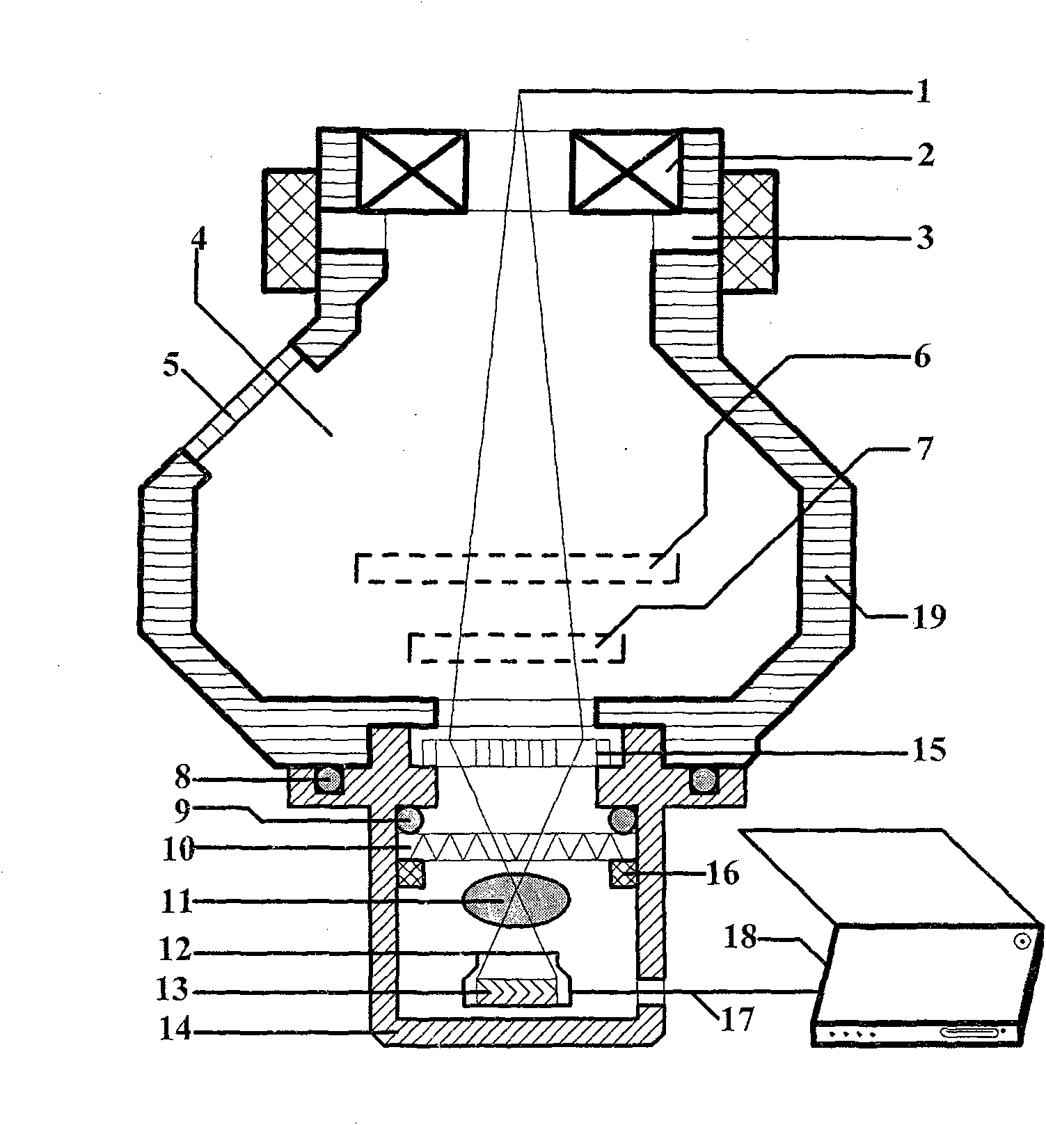
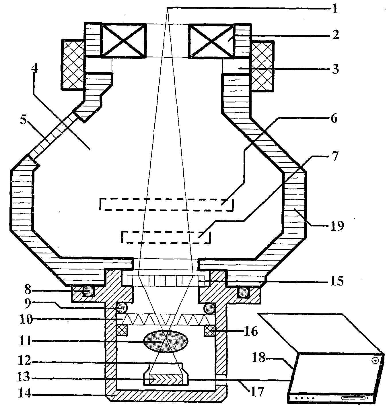
[0011] In the structure diagram of the present invention, the stainless steel base (14) is installed in the middle of the reserved screw hole (not shown in the figure) at the bottom of the projection chamber of the transmission electron microscope, and all other components except the computer (18) are installed on this stainless steel base ( 14) On top, from top to bottom are transmission electron fluorescent screen (15), lead glass (10), lens (11), digital single-lens reflex camera (12). Between the stainless steel base (14) and the projection chamber wall (19) and the lead glass (10), there are respectively a large O-shaped sealing ring (8) and a small O-shaped sealing ring (9) to act as a vacuum seal, and the O-shaped bracket (16) support the lead glass (10) and make the small O-shaped sealing ring (9) subject to proper pressure to ensure the sealing effect. The transmission electron fluorescent screen (15) has an effective diameter of 70mm and a circular shape (about 3800m...


PUM

PropertyMeasurementUnit
diameteraaaaaaaaaa

Abstract

The invention provides a device capable of recording a transmission electron image of a transmission electron microscope in real time in a mode of digital image. The device consists of a transmission electron phosphor screen, an optical lens, a digital single lens reflex camera, a computer and other auxiliary structures, and is characterized in that: the bottom part of a transmission electron microscope is provided with the transmission electron phosphor screen with a bigger area for converting the transmission electron image into the optical image; and the digital single lens reflex camera is arranged outside a projection room, the digital single lens reflex camera can convert the optical image into the digital image in real time by a wide-aperture value lens and send the image data to the computer, which is connected with the digital single lens reflex camera, by a usb 2.0 cable, the computer processes the image data so as to show the result in real time, and the exposure time and the light sensitivity of the digital single lens reflex camera are automatically controlled by software operated on the computer. The device can be used for replacing the electronic film of the transmission electron microscope to shoot the transmission electron images and the diffraction patterns.

Description

technical field [0001] The invention relates to a transmission electron microscope, in particular to a technical scheme and a device for recording transmission electron images and diffraction patterns of a transmission electron microscope in a digital image mode. Background technique [0002] The transmitted electron beam (1) reflecting the sample information is projected into the projection room (4) through the projection mirror (2), and the operator mainly observes the transmitted electron image on the main fluorescent screen (6) through the lead glass window (5). (7) Record the image. When the main fluorescent screen (6) is lifted when the film is not being shot, the transmitted electrons can be projected to the bottom of the projection chamber (4). Traditionally, the transmission electron microscope uses film (7) to record the transmission electron image and diffraction pattern information of the sample. At present, in the domestic market, Gatan, TVIPS, and Soft Imagin...

Claims


Application Information

Patent Timeline
Patent Type & Authority Applications(China)
IPC IPC(8): G01N23/04H04N5/225H04N5/232H01J37/28
Inventor 刘冰川曲利娟刘庆宏
Owner FUZHOU GENERAL HOSPITAL OF NANJING MILITARY COMMAND P L A
Why Eureka
Try Eureka