Easy-maintenance floating ballast bed
A technology of floating ballast bed and easy maintenance, which is applied in the field of ballast bed, and can solve problems such as interruption of rail operation traffic, corrosion, and damage to supporting blocks, so as to prolong the service cycle and service life, broaden the prospect of popularization and application, and have good buffering and vibration isolation effects Effect
- Summary
- Abstract
- Description
- Claims
- Application Information
AI Technical Summary
Problems solved by technology
Method used
Image
Examples
Embodiment 1
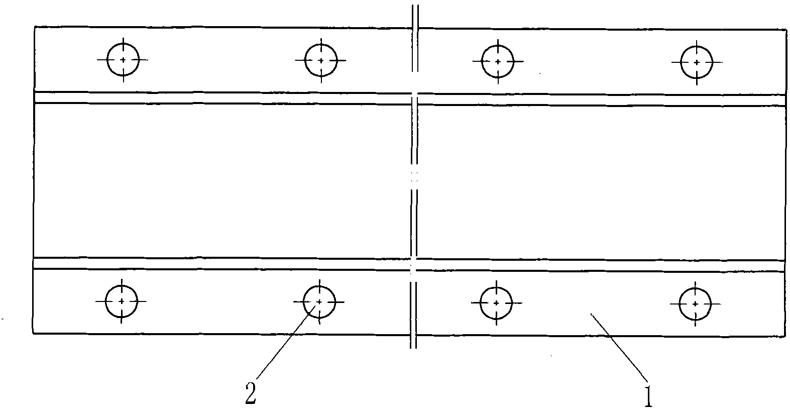
[0021] like figure 1 , figure 2 , image 3 , Figure 4 As shown, the easy-to-maintain floating ballast bed of the present invention includes a floating plate 1 and an elastic vibration isolator 2, the elastic vibration isolator 2 is arranged in the reserved through hole of the floating plate 1, and a supporting block is arranged on the inner wall of the through hole 3. The floating plate 1 is supported on the elastic vibration isolator 2 through the support block 3. Four blind holes are reserved on the concrete structure of the inner wall of the through hole of the floating plate, and the support block 3 is partially inserted into the blind holes. The elastic vibration isolator 2 used in this example is a helical steel spring vibration isolator with a silicone oil liquid damping material inside, and the supporting block is made of ordinary carbon steel material and has been subjected to hot-dip galvanized anti-corrosion treatment.
[0022] In order to protect the blind hol...
Embodiment 2
[0029] like Image 6 As shown, the difference from Embodiment 1 is that a coupling sleeve 10 is pre-embedded in the reserved through hole of the floating plate 1 , and a relief through hole is provided on the coupling sleeve 10 corresponding to the position of the supporting block 3 . A bushing 4 made of ceramics is partially arranged in the blind hole of the block supporting the block. In order to prevent the support block 3 from moving horizontally, a limit plate 7 is welded on the coupling sleeve 10, and a positioning pin 8 is used to position and prevent slippage between the limit plate 7 and the support block 3 . In order to facilitate jacking, a jacking block 11 is also provided on the top of the coupling sleeve 10, and the dust cover 9 is fixed on the jacking block 11. The elastic vibration isolator 2 used in this embodiment is a helical steel spring vibration isolator with rubber solid damping material inside.
[0030] In order to prevent relative movement between th...
Embodiment 3
[0033] like Figure 7 As shown, the difference from Example 1 is that naked blind holes are set on the concrete inner wall of the through-holes reserved for the floating slab. In order to prevent water storage, the blind holes are all inclined. The main force direction of the block 3 is upward, and such an inclined structure can also effectively prevent the support block from breaking out of the hole. But in order to ensure that the support block can not move, after the jacking is completed, a limit plate 13 is set above the gasket 5 and in the middle of the support block to withstand the support block. In addition, for the convenience of jacking, a jacking block 11 is preset on the floating plate 1 . In order to strengthen the strength of the blind hole, a reinforced mesh 30 is provided around the blind hole with stainless steel bars to meet the requirement of a design life of 100 years. If ordinary steel bars are used as reinforced steel mesh, there should be a layer of co...
PUM
 Abstract
Description
Claims
Application Information
 - R&D Engineer
- R&D Manager
- IP Professional
- Industry Leading Data Capabilities
- Powerful AI technology
- Patent DNA Extraction
Browse by: Latest US Patents, China's latest patents, Technical Efficacy Thesaurus, Application Domain, Technology Topic, Popular Technical Reports.
© 2024 PatSnap. All rights reserved.Legal|Privacy policy|Modern Slavery Act Transparency Statement|Sitemap|About US| Contact US: help@patsnap.com


