Low-orbit aircraft based on aerodynamic attitude control and attitude control method thereof
An attitude control and aerodynamic technology, which is applied to the guidance devices of space navigation vehicles, etc., can solve the problems of short on-orbit life and large fuel consumption of aircraft, and achieve the effect of improving life and increasing propellant carrying capacity.
- Summary
- Abstract
- Description
- Claims
- Application Information
AI Technical Summary
Problems solved by technology
Method used
Image


Examples
specific Embodiment approach 1
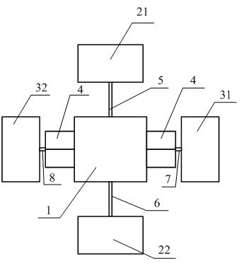
[0014] Specific implementation mode one : the low-orbit vehicle based on aerodynamic attitude control of the present embodiment, which includes aircraft body 1, pitching attitude control aerodynamic auxiliary board, yaw attitude control aerodynamic auxiliary board, first rotating mechanical arm 5, second rotating mechanical arm arm 6, the third rotating mechanical arm 7 and the fourth rotating mechanical arm 8, wherein the pitching attitude control aerodynamic auxiliary board is composed of a first aerodynamic auxiliary board 21 and a second aerodynamic auxiliary board 22, and the yaw attitude The control aerodynamic auxiliary board is composed of a third aerodynamic auxiliary board 31 and a fourth aerodynamic auxiliary board 32;
[0015] One end of the first rotating mechanical arm 5, one end of the second rotating mechanical arm 6, one end of the third rotating mechanical arm 7 and one end of the fourth rotating mechanical arm 8 are respectively connected to the tail of the...
specific Embodiment approach 2
[0018] Specific implementation mode two : Different from Embodiment 1, this embodiment also includes two wedge-shaped ailerons 4, and the cross-section of the wedge-shaped ailerons (4) is wedge-shaped, and one of the wedge-shaped ailerons 4 is located on the left side of the aircraft body 1 and It is connected with the left side surface of the aircraft body 1 , and another wedge-shaped aileron 4 is located at the right side of the aircraft body 1 and connected with the right side surface of the aircraft body 1 .
[0019] Each wedge-shaped aileron 4 is a sealed body composed of five plates, wherein the five plates include three rectangular plates of the same specification and two triangular plates, and the three rectangular plates are connected end to end in turn to form a hollow triangle For a cylinder, the two triangular plates are respectively placed on the upper bottom surface and the lower bottom surface of the triangular cylinder, and the joints of the five plates are al...
specific Embodiment approach 3
[0024] Specific implementation mode three: Different from Embodiment 1, this embodiment also includes a first aerodynamic auxiliary board aileron 9, a second aerodynamic auxiliary board aileron 10, a fifth rotating mechanical arm 11 and a sixth rotating mechanical arm 12, wherein the fifth One end of the rotating mechanical arm 11 is connected to the left side of the aircraft body 1, one end of the sixth rotating mechanical arm 12 is connected to the right side of the aircraft body 1, and the other end of the fifth rotating mechanical arm 11 is connected to the first aerodynamic auxiliary plate aileron 9, And the first aerodynamic auxiliary plate aileron 9 can be driven to rotate with the central axis of the fifth rotating mechanical arm 11 as the central axis, and the other end of the sixth rotating mechanical arm 12 is connected to the second aerodynamic auxiliary plate aileron 10, and the second aerodynamic auxiliary plate aileron 10 can be driven to rotate around the cent...
PUM
 Abstract
Description
Claims
Application Information
 - Generate Ideas
- Intellectual Property
- Life Sciences
- Materials
- Tech Scout
- Unparalleled Data Quality
- Higher Quality Content
- 60% Fewer Hallucinations
Browse by: Latest US Patents, China's latest patents, Technical Efficacy Thesaurus, Application Domain, Technology Topic, Popular Technical Reports.
© 2025 PatSnap. All rights reserved.Legal|Privacy policy|Modern Slavery Act Transparency Statement|Sitemap|About US| Contact US: help@patsnap.com