Drilling jig for speed reducer connecting cover

A drilling jig and connecting cover technology, applied in drilling/drilling equipment, clamping, manufacturing tools, etc., can solve the problems of low production efficiency and difficulty in ensuring the position of holes, and achieve high production efficiency and high positional accuracy. The effect of small error and simple structure

Inactive Publication Date: 2010-07-28
HANGZHOU JIACHENG MACHINERY
View PDF1 Cites 15 Cited by
  • Summary
  • Abstract
  • Description
  • Claims
  • Application Information

AI Technical Summary

Problems solved by technology

[0004] The invention mainly solves the problems in the prior art that the position of the hole is difficult to guarantee and the production efficiency is relatively low, and provides a reducer connection cover drilling jig with a simple structure, relatively small error in the position of the hole, and relatively high production efficiency

Method used


Image

  • Drilling jig for speed reducer connecting cover
  • Drilling jig for speed reducer connecting cover
  • Drilling jig for speed reducer connecting cover

Examples


Embodiment 1

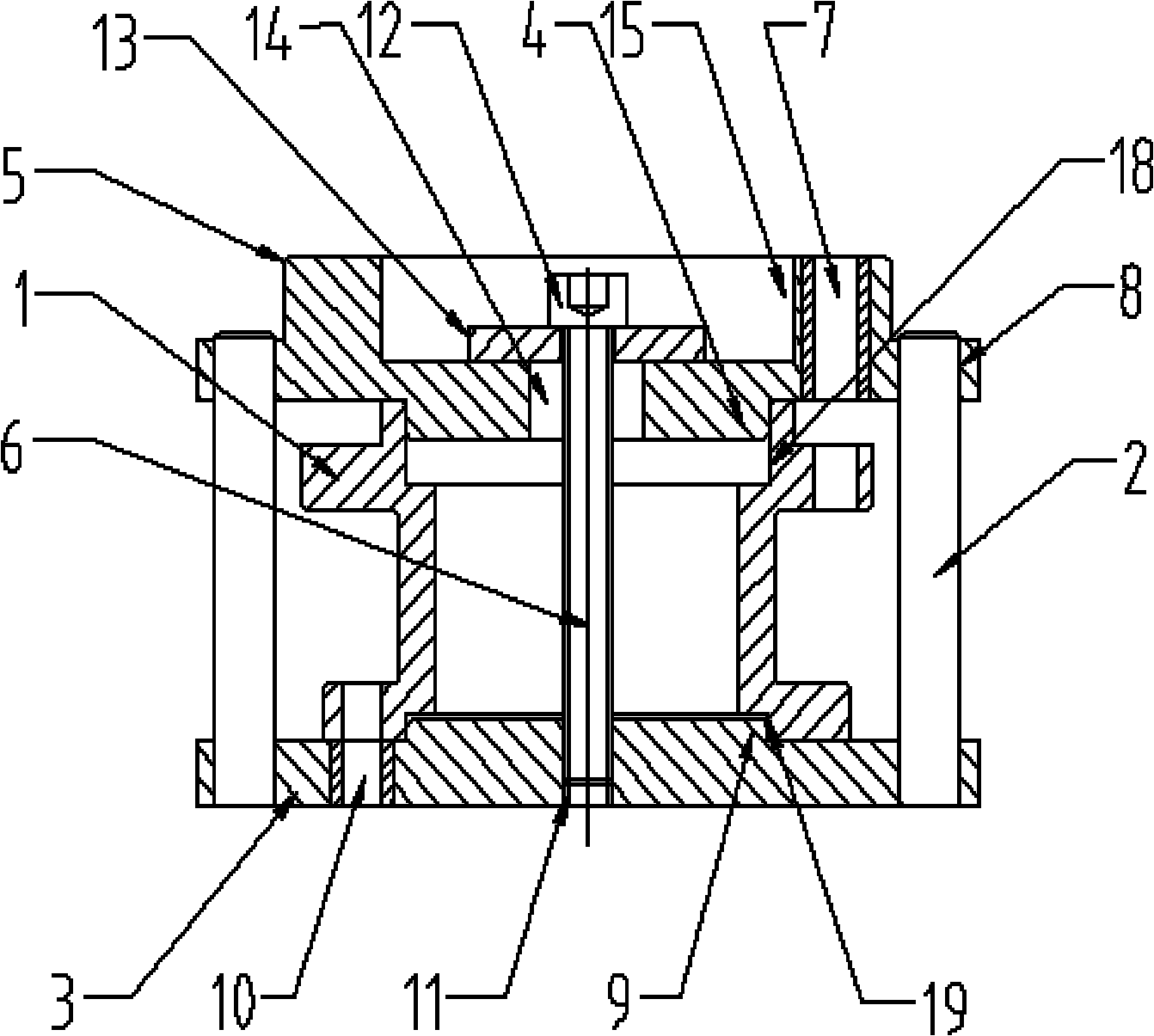
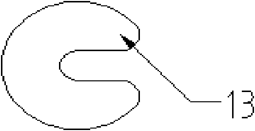
[0013] Embodiment 1: A drilling jig for the connection cover of the reducer, see the attached figure 1 And attached figure 2 , including the reducer connection cover 1, the bottom surface of the reducer connection cover 1 is provided with a lower formwork 3, and the lower formwork 3 is provided with a positioning boss 9, a guide hole 10, a threaded hole 11 and a guide post 2 perpendicular to the lower formwork 3, The center of the reducer connection cover 1 is provided with a clamping device 6, the clamping device 6 is composed of a hexagon socket head cap screw 12 and an opening gasket 13, an upper template 5 is provided on the reducer connection cover 1, and a positioning plate 5 is provided on the upper template 5. The boss 4, the guide hole 7 and the guide post hole 8, the upper template 5 is slidably connected with the guide post 2 through the guide post hole 8, and the upper surface of the upper template 5 is provided with a through hole 14 and The counterbore 15 that ...

Embodiment 2

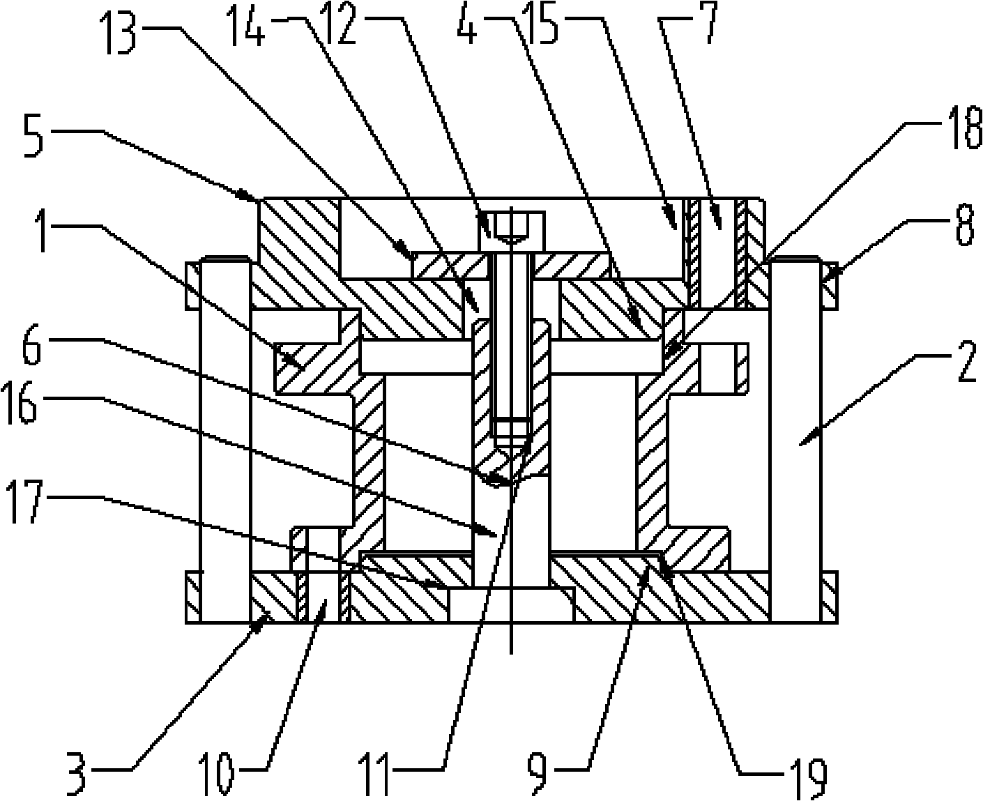
[0015] Embodiment 2: Another gear reducer connection cover drilling jig, as attached image 3 As shown, the lower template 3 is provided with a stepped hole 17, and the lower template 3 is provided with a column 16 of a stepped shaft, the column 16 and the stepped hole 17 are interference fit, and the threaded hole 11 is located at the top of the column 16, and the remaining structures and processing methods are the same as Example 1 is the same.


PUM


Abstract

The invention discloses a drilling jig for a speed reducer connecting cover and aims to provide the drilling jig for the speed reducer connecting cover, which has a simple structure, small hole position errors and high production efficiency. The drilling jig comprises the speed reducer connecting cover (1), a lower template (3) provided with a guide post (2), an upper template (5) provided with a positioning lug boss (4), and a clamping device (6), wherein the upper template (5) is provided with a guide hole (7) and a guide post hole (8) and is connected with the guide post (2) in a sliding way through the guide post hole (8); the lower template (3) is provided with a positioning lug boss (9), a guide hole (10) and a screw hole (11); the clamping device (6) consists of a screw (12) and an open spacer (13) and is arranged in the center of a jig body; and the upper surface of the upper template (5) is provided with a through hole (14) through which the entire screw (12) can pass and a counter bore (15) into which the tail of the screw (12) and the open spacer (13) can sink. The drilling jig can realize the processing of holes on two surfaces with certain position requirements on an ordinary drilling machine.

Description

technical field [0001] The invention relates to a drilling jig, in particular to a jig for processing holes with relative positions on both surfaces of a connection cover of a reducer. Background technique [0002] The connection cover of the reducer has a cylindrical structure, with a through hole in the center and flanges with stepped holes at both ends. There are 4 holes on the circumference of the lower flange and 6 holes on the circumference of the upper flange, which are connected with the left and right deceleration respectively. If the machine is rigidly connected, the requirements for the relative position of the holes are relatively high. In the prior art, ordinary drilling machines are generally used for processing, and two sets of fixtures are usually used. Firstly, the bottom surface faces upwards, and the bottom surface is provided with a lower template with guide holes, screws, pressure plates and positioning bosses, and the lower flange step holes are used fo...

Claims


Application Information

Patent Timeline
Patent Type & Authority Applications(China)
IPC IPC(8): B23Q3/00B23B47/00
Inventor 叶张水王坚
Owner HANGZHOU JIACHENG MACHINERY
Why Eureka
Try Eureka