Developer unit for an electrophotographic printing device for printing on glass or ceramic material

A technology of electrophotographic printing and developing unit, which is applied in the field of toner supply and toner application device, electrophotographic printing equipment, and can solve problems such as inaccuracy and uneven application of toner

Inactive Publication Date: 2010-07-21
AGC FLAT GLASS EUROPE SA
View PDF0 Cites 4 Cited by
  • Summary
  • Abstract
  • Description
  • Claims
  • Application Information

AI Technical Summary

Problems solved by technology

Accounting for diameter tolerances, inaccuracies and sags in circular motion, distance and nip at the photoconductor can vary and make toner application uneven

Method used


Image

  • Developer unit for an electrophotographic printing device for printing on glass or ceramic material
  • Developer unit for an electrophotographic printing device for printing on glass or ceramic material
  • Developer unit for an electrophotographic printing device for printing on glass or ceramic material

Examples


Embodiment Construction

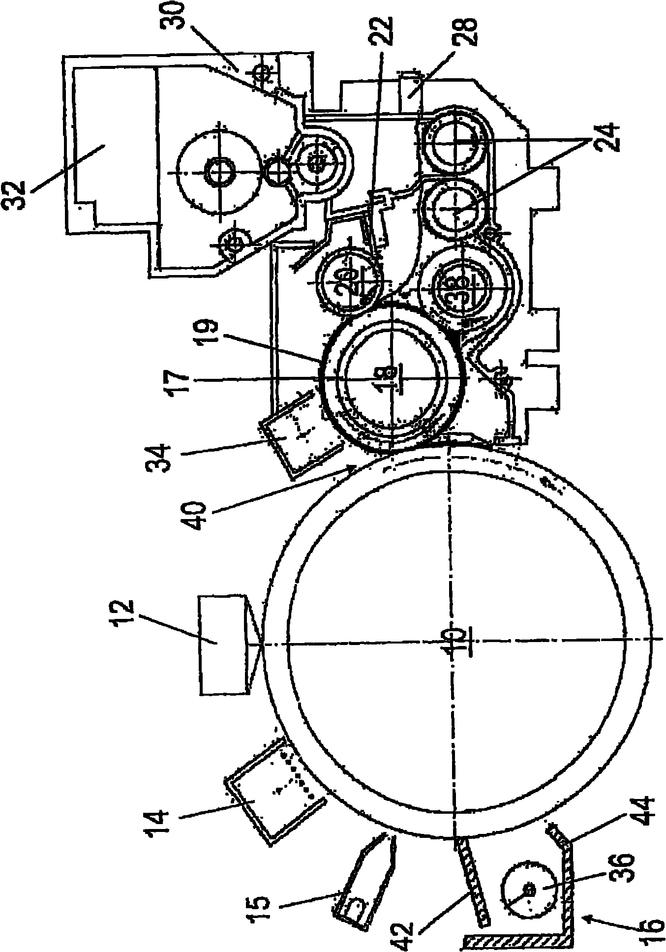
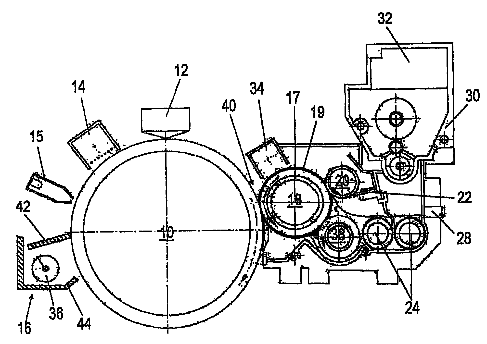
[0025] Via a toner attachment 30, which has an incorporated toner supply (not specifically shown), toner is conveyed from the toner cartridge to the area of ​​two conveying and mixing screws 24 that rotate in opposite directions. The level sensor 28 reports the correct fill level to an electronic controller (not shown) of the printing apparatus. The electronic controller requests new toner as needed based on the sensor signal.

[0026] The single loop system formed by the conveying and mixing screw 24 conveys the toner to an application roller 38 which rotates in a counterclockwise direction. The applicator roller 38 consists essentially of a material that charges the coating 19 of the developer roller 18 by triboelectric charging, such as EPDM, NBR or PU foam. The applicator roll 38 has a width of about 960 mm, a diameter of about 50 mm, a Shore A hardness of about 50° and a perforation size of about 200 μm. Via the connection of the bias voltage to the inner mandrel, a bia...


PUM


Abstract

The invention relates to a developer unit for an electrophotographic printing device for printing on glass or ceramic material having a toner supply (30, 32) and a toner application device (38), toner being discharged onto a developer device (18) by means of the toner application device (38) and it being possible for the developer device (18) to be brought into flat contact with a photoconductor (10). According to the invention, the developer device (18) has a fibre coating (19) of electrically conductive fibres, which picks up the toner and is in contact with the photoconductor (10) in order to transfer the toner.

Description

technical field [0001] The present invention relates to a developing unit of an electrophotographic printing apparatus for printing on glass or ceramic materials, having a toner supply and a toner application device through which toner is released onto the developing unit and The developing device can be brought into flat contact with the photoconductor. [0002] Furthermore, the present invention also relates to an electrophotographic printing apparatus for printing on glass or ceramic materials having such a developing unit. Background technique [0003] The prior art discloses a developing unit in which a relatively high pressure is generated due to the strong mechanical contact between the developing roller on the one hand and the photoconductor on the other hand between the developing roller, the metering roller and the application roller. Due to these pressures, at high printing speeds, the toner particles partially melt, smear and form a film-like application. The a...

Claims


Application Information

Patent Timeline
IPC IPC(8): G03G15/08
CPCG03G15/0805
Inventor 迪特尔·琼安德烈亚斯·舍恩伯格克里斯琴·霍尼科尔
Owner AGC FLAT GLASS EUROPE SA
Why Eureka
Try Eureka