
Composite excitation generator rotor

A generator rotor and compound excitation technology, which is applied to the rotating parts of the magnetic circuit, the manufacture of the stator/rotor body, the shape/style/structure of the magnetic circuit, etc., can solve the problems of inconvenient assembly, easy throwing of the magnetic steel, unsafe etc. problem, achieve the effect of improving work efficiency and easy assembly

Inactive Publication Date: 2010-07-21
杨万红
View PDF0 Cites 1 Cited by
  • Summary
  • Abstract
  • Description
  • Claims
  • Application Information

AI Technical Summary

Problems solved by technology

[0002] In the rotor of the compound excitation generator in the prior art, the rotating shaft is press-fitted in the center hole of the rotor iron core. The rotor iron core is composed of several rotor iron chips. In the magnetic steel groove, the magnetic steel installed in this structure is easy to throw out when rotating at high speed, which is extremely unsafe.
The enameled wire is wound in the frame groove of the coil frame, put the nut in the nut groove of the "T"-shaped screw nut groove, install the insulating pressure plate and the pressure plate on the outside of the coil, and fasten them in the nut with bolts, through the insulation pressure plate and the pressure plate The coil is pressed tightly in the frame groove of the coil frame; the nut groove in the screw nut groove of this structure is designed at one end of the "T" deep groove, and the nut groove and the extending end of the screw are placed in the same room, When assembling, the nut is easy to slip in the nut groove, therefore, it is very inconvenient to assemble, moreover, it is labor-intensive and time-consuming

Method used


Image

  • Composite excitation generator rotor
  • Composite excitation generator rotor
  • Composite excitation generator rotor

Examples


Embodiment Construction

[0015] Describe the present invention in detail below in conjunction with accompanying drawing:

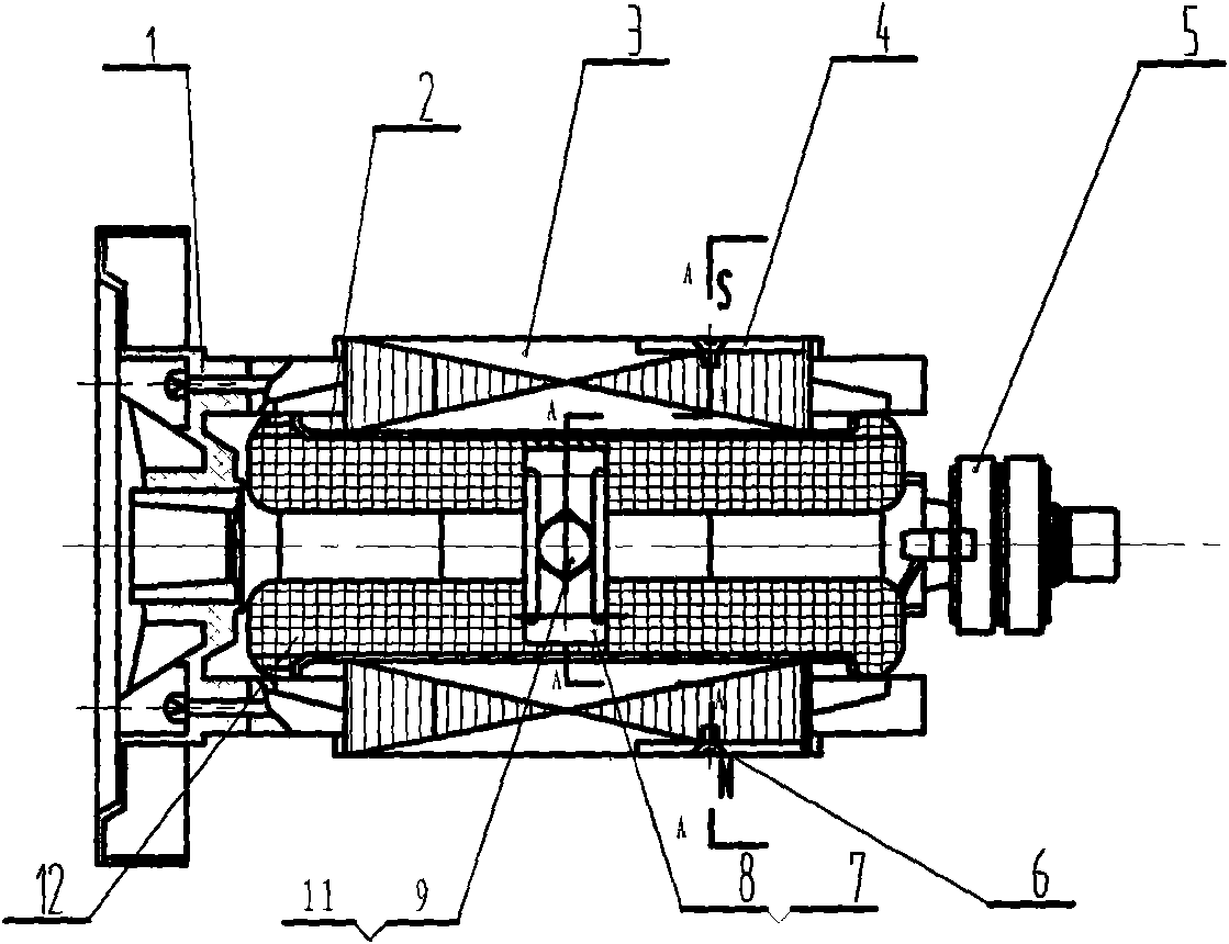
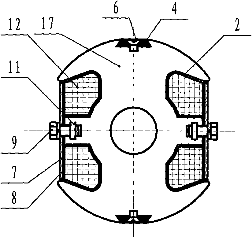
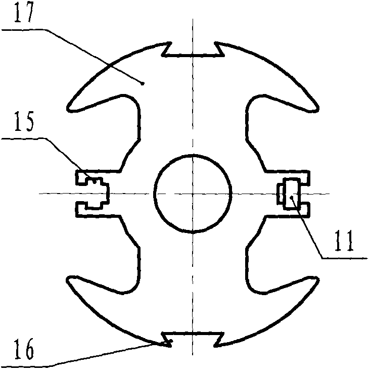
[0016] Such as Figure 1-3 As shown, the composite excitation generator rotor, the rotor core 3 is composed of several rotor cores 17, and the rotating shaft is press-fitted in the central hole of the rotor core 3. The dovetail-shaped magnetic steel groove 16 provided on the rotor core 3 is equipped with a magnetic steel 4. In order to ensure that the magnetic steel 4 will not be thrown out during high-speed rotation, the assembly structure of the magnetic steel 4 is adopted in the dovetail-shaped magnetic steel A screw hole is formed at the bottom center position of the groove 16, and a countersunk screw 6 is correspondingly formed on the magnetic steel 4, and the magnetic steel 4 is fastened on the dovetail magnetic steel groove 16 in the hole. The enameled wire 12 is wound in the frame groove of the coil frame 2, the nut 11 is put in the nut groove of the screw nut groove 15 o...


PUM


Abstract

The invention belongs to the technical field of a motor, particularly relates to a composite excitation generator rotor. The rotor is characterized in that the bottom of a dovetail-shaped magnetic steel groove is provided with a thread hole; the magnetic steel is correspondingly provided with a countersunk screw hole, and a screw is arranged in the countersunk screw hole; the magnetic steel is fastened on the dovetail-shaped magnetic steel groove; screw and nut grooves are designed into a cross shape, the size of the nut groove is basically the same as the size of the nut. As the bottom of the dovetail-shaped magnetic steel groove on a punching sheet is provided with the thread hole, the magnetic sheet is inserted into the groove during installation, and then is fastened by the screw, thereby ensuring the magnetic steel not to throw away in high-speed rotation. As the screw and nut grooves are designed into the cross shape, and the size of the nut groove is basically the same as the size of the nut, the screw can not slide in the groove, the position used for the screw head in the nut grove is reserved, and the nut can be assembled by a long bolt, thereby being easy to assemble and enhancing the working efficiency.

Description

Technical field: [0001] The invention belongs to the technical field of motors, and in particular relates to a composite excitation generator rotor. Background technique: [0002] In the rotor of the compound excitation generator in the prior art, the rotating shaft is press-fitted in the center hole of the rotor iron core. The rotor iron core is composed of several rotor iron chips. In the magnetic steel groove, the magnetic steel installed in this structural form is easy to throw out when rotating at high speed, which is extremely unsafe. The enameled wire is wound in the frame groove of the coil frame, put the nut in the nut groove of the "T"-shaped screw nut groove, install the insulating pressure plate and the pressure plate on the outside of the coil, and fasten them in the nut with bolts, through the insulation pressure plate and the pressure plate The coil is pressed tightly in the frame groove of the coil frame; the nut groove in the screw nut groove of this struct...

Claims


Application Information

Patent Timeline
Patent Type & Authority Applications(China)
IPC IPC(8): H02K15/02H02K1/22
Inventor 杨正荣李桂曙
Owner 杨万红
Learn More