
Wind generator all-in-one machine

An all-in-one machine and fan technology, used in wind turbines, wind turbine combinations, wind power generation, etc., can solve the problem that wind turbines are not suitable for wireless sensor networks and distributed small system power supply, etc. Improve efficiency and protect the environment

Active Publication Date: 2010-07-21
日照瑞达建设集团有限公司
View PDF2 Cites 5 Cited by
  • Summary
  • Abstract
  • Description
  • Claims
  • Application Information

AI Technical Summary

Problems solved by technology

[0004] The invention solves the problem that the traditional wind generator is not suitable for supplying power to wireless sensor networks and distributed small systems, and provides an integrated wind power generator suitable for supplying power to wireless sensor networks and distributed small systems

Method used


Image

  • Wind generator all-in-one machine
  • Wind generator all-in-one machine
  • Wind generator all-in-one machine

Examples


Embodiment 1

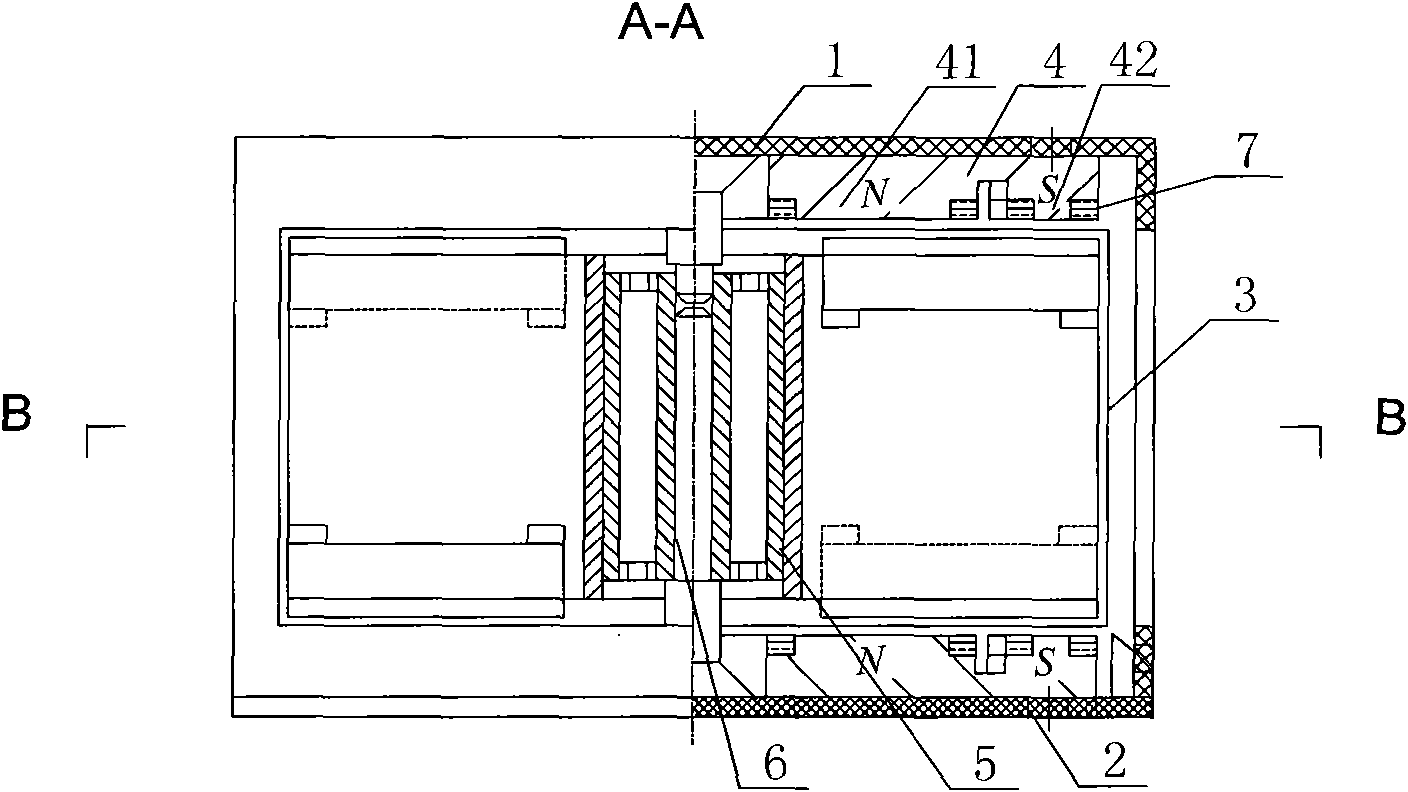
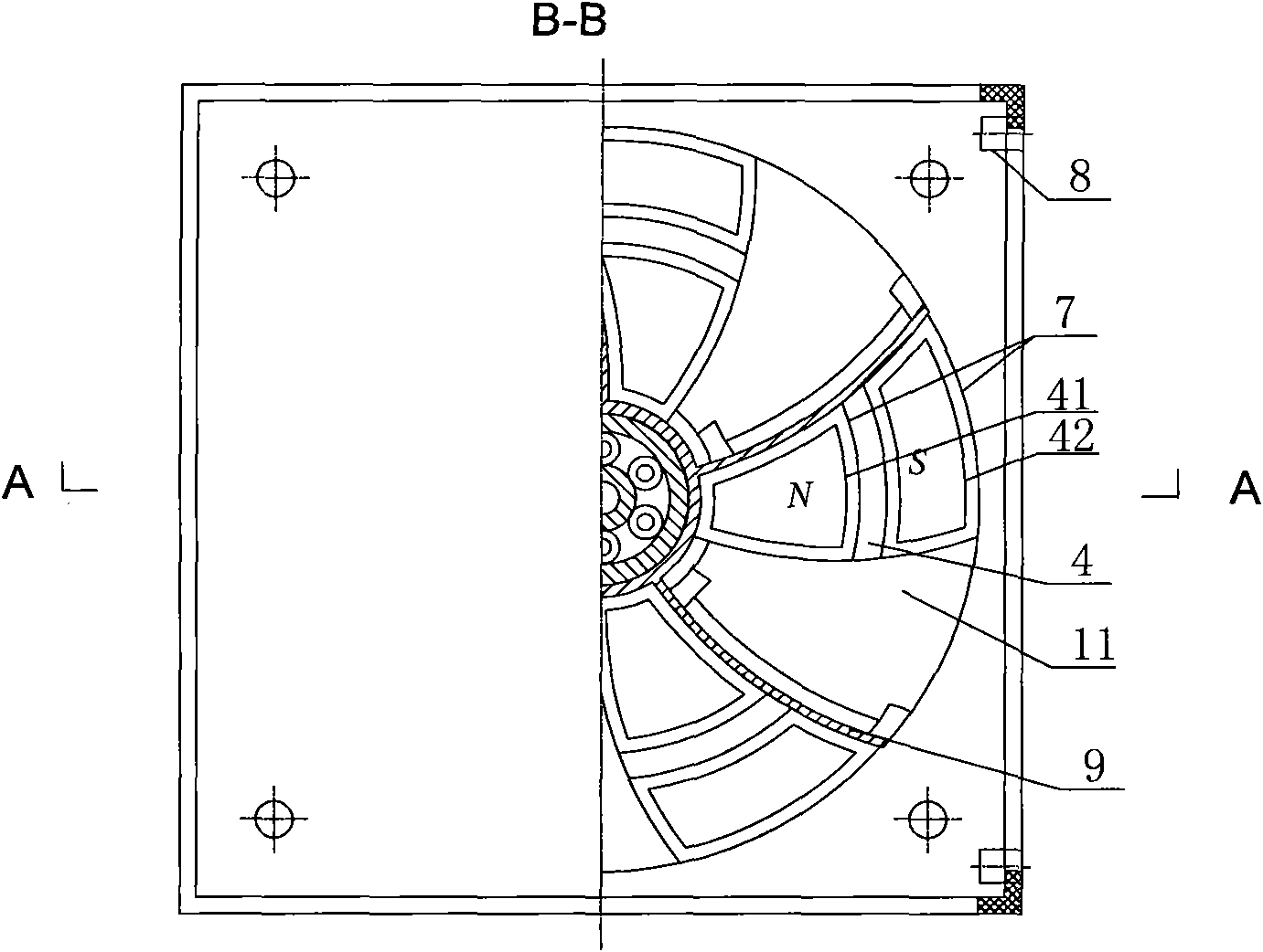
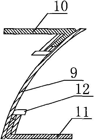
[0021] refer to Figure 1-3 , The integrated wind power generator of the present invention includes a vertical axis fan 3, and the vertical axis fan 3 of non-magnetic material is installed between the upper fan cover 1 and the lower fan base 2 through the shaft 6 and the bearing 5. The fan cover 1 is installed on the fan base 2 through four card holders 8 . Permanent magnets 4 are provided on the inner sides of the fan cover 1 and the fan base 2 , and the permanent magnets 4 include a permanent magnet N pole 41 and a permanent magnet S pole 42 . The permanent magnets 4 are evenly arranged circumferentially around the fan shaft 6 , and are fixed on the fan cover 1 or the fan base 2 by bonding. Both the N pole 41 of the permanent magnet and the S pole of the permanent magnet are wound with a coil 7 , and the coil can also be fixed on the permanent magnet 4 by means of bonding. Each fan blade 9 on the vertical axis fan 3 is different from the ordinary fan blade, and has a fan b...

Embodiment 2

[0026]The difference between this embodiment and the first embodiment is that the number of permanent magnets 4 on the fan cover 1 and fan base 2 is twice the number of fan blades 9 respectively. Assuming that the fan 3 includes 6 fan blades as in the first embodiment, the analysis similar to the first embodiment shows that the total electromotive force obtained is 24 times of the electromotive force generated by each coil 7 .


PUM


Abstract

The invention relates to a wind generator all-in-one machine which comprises a vertical shaft fan made of non-conduction magnetic material. The shaft of the vertical shaft fan is arranged on an upper fan cover and a lower fan base. A plurality of permanent magnets are respectively arranged at the inner sides of the fan cover and the fan base, and are uniformly arranged around the fan shaft in the circumferential direction. The pole of the permanent magnet near the fan shaft is opposite to the pole of the permanent away from the fan shaft. The N poles and the S poles of the permanent magnets are respectively wound with coils. The upper end and the lower end of the vertical shaft fan are respectively provided with a vane upper edge and a vane lower edge which are respectively made of soft magnetic material. The shapes of the vane upper edge and the vane lower edge are the same with the shape of the permanent magnet. The N poles of the permanent magnets, the vane upper edge or the vane lower edge, and the S poles of the permanent magnets form a plurality of closed main magnetic circuits with gaps. When the vanes rotates, the magnetic flux of each coil is increased or decreased along with the change of the magnetic conduction in each magnetic circuit, and then the alternating current motive force is generated. The invention has the advantages of compact structure, small volume, high energy conversion rate, energy saving and environment protection.

Description

technical field [0001] The invention relates to an integrated wind power generation machine, in particular to an integrated wind power generation machine suitable for wireless sensor networks and distributed small systems. Background technique [0002] With the emergence and development of wireless sensor networks, distributed small systems and the Internet, the problem of power supply of nodes that are scattered everywhere and make up the above systems has become a difficult problem. These nodes generally need to have their own independent power supply devices, most of which are batteries. However, the power of the battery is limited. Even if the low power consumption design is adopted for the wireless sensor node, it can only last for a few months. The battery life becomes the bottleneck of the node life. At the same time, most wireless sensor nodes are not recycled, so the chemical battery carried by the node can cause problems. The secondary pollution is bound to become...

Claims


Application Information

Patent Timeline
Patent Type & Authority Applications(China)
IPC IPC(8): F03D9/00H02K7/18F03D9/25
CPCY02E10/72
Inventor 张端郭慧贤何熊熊
Owner 日照瑞达建设集团有限公司
Learn More