
Double-faced robot head device

A robot and head technology, which is applied in the field of double-sided robot head devices, can solve the problems of inability to realize the movement of the double-sided robot head organs, complex and complicated structure, and high cost, and achieves reduced head size, convenient use, and high cost. low effect

Inactive Publication Date: 2010-07-21
SHANGHAI UNIV
View PDF5 Cites 14 Cited by
  • Summary
  • Abstract
  • Description
  • Claims
  • Application Information

AI Technical Summary

Problems solved by technology

[0003] The purpose of the present invention is to overcome the shortcomings of the existing robot head device, which are complex and cumbersome in structure, high in cost and unable to realize the movement of the head organs of the double-sided robot, and provide a double-sided robot head device with a simple and compact structure and low cost, which can effectively realize A mechanical device that imitates the movement of organs such as eyeballs, eyelids, and mouth on both sides of the head of a humanoid robot to make various robot facial expressions

Method used


Image

  • Double-faced robot head device
  • Double-faced robot head device
  • Double-faced robot head device

Examples


Embodiment 1

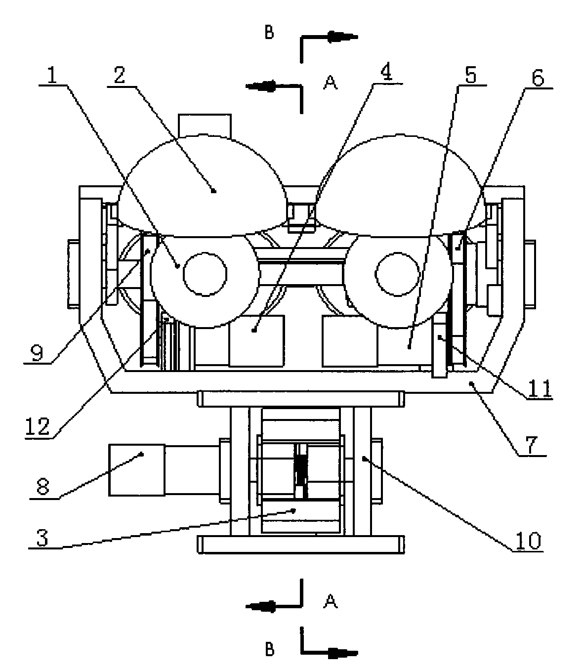
[0019] Embodiment one: see figure 1 , the double-sided robot head device includes an eye support frame 7, a mouth mounting frame 10, a four-eye horizontally rotating part 1, a four-eyelid part 2, a double-mouth part 3, and three micromotors—— A micro-motor one 4, a micro-motor two 5 and a micro-motor three 8, two synchronous belt transmission assemblies-a synchronous belt transmission assembly one 6 and a synchronous belt transmission assembly two 9; it is characterized in that the eye support frame 7 Fixedly connect the mouth installation frame 10 below, micromotor one 4 and micromotor two 5 are fixedly installed on the eye support frame 7, four eyeball horizontal rotating parts 1 are installed on the eye support frame 7, synchronous belt drive assembly two 9 and The four eyeball horizontally rotating parts 1 are connected, and the micro motor one 4 is driven by the synchronous belt transmission assembly two 9 to drive the four eyeball horizontally rotating part 1; the four e...

Embodiment 2

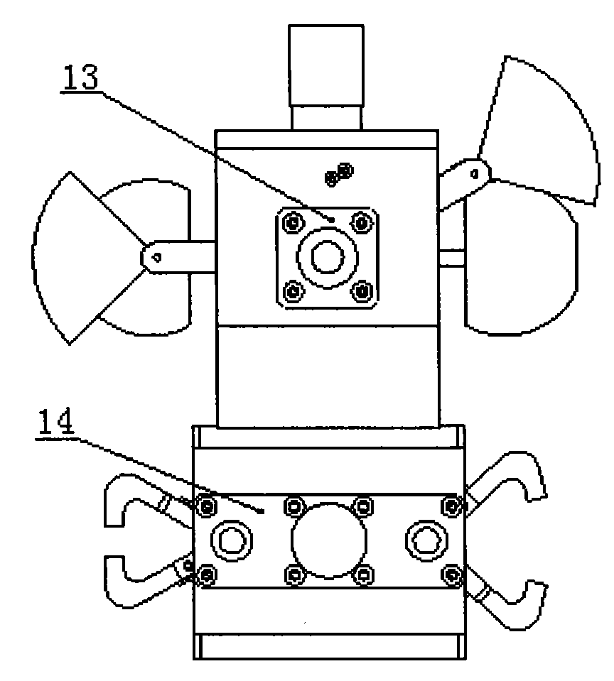
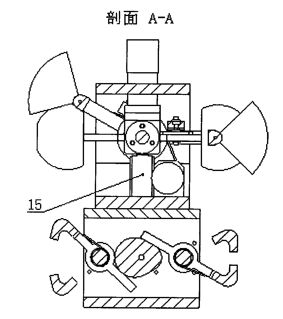
[0020] Embodiment 2: This embodiment is the same as Embodiment 1, and the special features are as follows: see figure 1 and figure 2 The two ends of the four-eye horizontally rotating part 1 are equipped with positioning sleeves and miniature bearings, the four-eyelid part 2 is installed on the four-eye horizontally rotating part 1, and axially positioned by the positioning sleeve, the four-eye horizontally rotating part 1 is set The two ends of the miniature bearings are supported through the through holes at both ends of the eye support frame 7, and two eye bearing end caps 13 are fixedly connected to the two sides of the eye support frame 7 for axial positioning; the micro motor two 5 and a The motor mounting plate one 11 is fixedly connected, the motor mounting plate one 11 is fixedly connected with the eye support frame 7; the micro motor one 4 is fixedly connected with a motor mounting plate two 12, and the motor mounting plate two 12 is fixedly connected with the eye s...


PUM


Abstract

The invention relates to a double-faced robot head device, which comprises an eye bracket, a mouth mounting frame, four eye horizontal rotating parts, four eyelid parts, two mouth parts, a micro motor 1, a micro motor 2, a micro motor 3, a synchronous belt driving component 1 and a synchronous belt driving component 2, wherein the bottom of the eye bracket is fixedly connected with the mouth mounting frame; the micro motor 1 and the micro motor 2 are fixedly arranged on the eye bracket; the four eye horizontal rotating parts are arranged on the eye bracket; micro motor 1 drives the four eye horizontal rotating parts through the transmission of the synchronous belt driving component 2; the four eyelid parts are arranged on the four eye horizontal rotating parts; the micro motor 2 drives the four eyelid parts through the transmission of the synchronous belt driving component 1; the two mouth parts are arranged on the mouth mounting frame; and the micro motor 3 is fixedly arranged on the mouth mounting frame, and the two mouth parts are driven by the micro motor 3. The device is simple and compact in structure and low in cost and can effectively realize the motions of organs such as eyeballs, eyelids or mouths on two faces of a humanoid robot head.

Description

technical field [0001] The patent of the present invention relates to a robot head device, especially a double-sided robot head device. Background technique [0002] The humanoid robot is an ideal robot that can interact with people and provide services for people to bring a convenient life. In recent years, with the development of the economy, research on humanoid robots has become more and more in-depth, and robot head devices that can realize the movement of humanoid robot heads such as eyeballs, eyelids, and mouth have also developed accordingly. Existing robot head devices generally use various driving elements to drive the rotation of the robot's head organs, thereby realizing the movement of the humanoid robot's head, eyeballs, eyelids, mouth and other organs, and making various mechanical devices for robot facial expressions . Generally, the head device of a robot can only realize the movement of the head organ on one side of the robot, but it cannot do anything fo...

Claims


Application Information

Patent Timeline
Patent Type & Authority Applications(China)
IPC IPC(8): B25J19/00
Inventor 周潘伟谈士力张海洪蔡征宇梁加佳
Owner SHANGHAI UNIV
Learn More