


Quick Research
Generate reliable direction feasibility study reports for your R&D in just a few steps.

Technical Q&A
Discover and master advanced knowledge NOW. Basics, ideas, possibilities, all at once.

Find Solutions
As an expert in R&D theories, this can generate solutions to your technical problems instantly.

Evaluate Feasibility
Analyze your overall solution with one click, know your potential R&D risks in advance.

Monitor Landscape
Get weekly tech updates, stay abreast of the latest tech innovations and key insights.
Thread-laying device
A wire and laying technology, applied in the direction of transportation and packaging, delivery of filamentous materials, thin material processing, etc., can solve problems such as danger, and achieve the effect of quick disassembly and stable gap width
- Summary
- Abstract
- Description
- Claims
- Application Information
AI Technical Summary
Problems solved by technology
Method used
Image

Examples
Embodiment Construction
[0029] The illustrations in the individual figures represent the content according to the invention in a very simplified manner and are not to be understood as being true to scale. The individual components according to the content of the invention are shown in such a way that their structures can be well visualized.
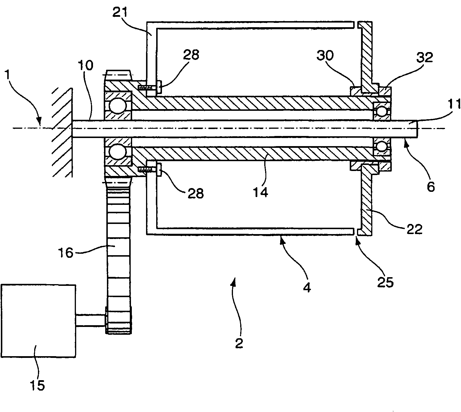
[0030] figure 1 The thread laying device according to the invention is shown in transverse section. The thread depositing device has a depositing drum 2 rotatable by a drive about an axis of rotation 1 , which forms a cylindrical surface 4 . The axis of rotation 1 is formed by a shaft 6 with one two shaft ends. The shaft 6 is rigidly mounted on the wire laying device. One shaft end is formed as an assembly shaft end 10, so that the shaft 6 is mounted on the wire laying device via the assembly shaft end 10, and the second shaft end 11 is formed as a free shaft end to form a single side for the laying drum 2. support. The laying drum 2 has a hollow shaft 14 ,...
PUM
 Abstract
Description
Claims
Application Information
 - R&D Engineer
- R&D Manager
- IP Professional
- Industry Leading Data Capabilities
- Powerful AI technology
- Patent DNA Extraction
Browse by: Latest US Patents, China's latest patents, Technical Efficacy Thesaurus, Application Domain, Technology Topic, Popular Technical Reports.
© 2024 PatSnap. All rights reserved.Legal|Privacy policy|Modern Slavery Act Transparency Statement|Sitemap|About US| Contact US: help@patsnap.com