
Quick cylindrical workpiece code word machine

A cylindrical, code word machine technology, applied in printing, stamping and other directions

Active Publication Date: 2012-04-11
HUAWEI TEHCHNOLOGIES CO LTD
View PDF2 Cites 0 Cited by
  • Summary
  • Abstract
  • Description
  • Claims
  • Application Information

AI Technical Summary

Problems solved by technology

But it still has some structural defects, the processing speed is relatively slow, and the adjustment is not very convenient

Method used


Image

  • Quick cylindrical workpiece code word machine
  • Quick cylindrical workpiece code word machine
  • Quick cylindrical workpiece code word machine

Examples


Embodiment Construction

[0017] The present invention will be further described below in conjunction with the embodiments and accompanying drawings.

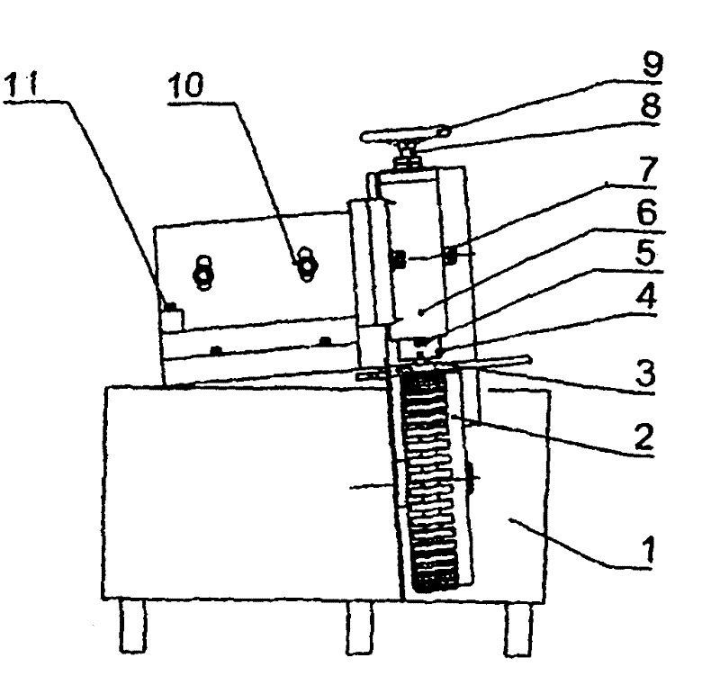
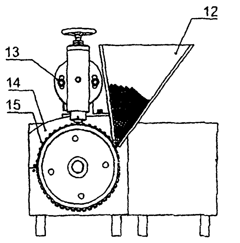
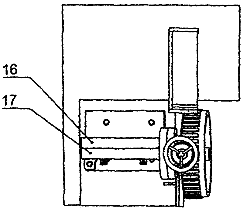
[0018] see Figure 1-Figure 3 , a cylindrical workpiece coding machine, which includes a machine base 1, a main shaft 8, a font box 4 and a font 3, a motor and a gearbox thereof, a built-in motor and a gearbox thereof in the frame 1, and the font box 4 positions and clamps the font 3 , the base 1 is obliquely equipped with a circular feeding tray 2 for clamping and conveying a cylindrical workpiece 15, the rear side of the circular feeding tray 2 is equipped with a baffle plate 14 that limits the axial position of the cylindrical workpiece 15, and the baffle plate 14 is arranged along the circle. The axial direction of the shaped feeding tray 2 moves, the support 16 is fixedly obliquely mounted on the base 1, the main shaft seat plate 17 supporting the main shaft 8 is installed on the support 16 with the adjusting screw 10, and the annular screw is prov...


PUM


Abstract

The invention discloses a cylindrical workpiece code work machine, which comprises a machine base, a main shaft, a matrix box and matrices, a motor and a gearbox of the motor, wherein the motor and the gearbox of the motor are arranged in the machine base; the matrices are tightly clamped by the matrix case; a round feeding disc is arranged on the machine base in an inclined way; a baffle is arranged on the rear side of the round feeding disc; a bracket is fixedly arranged on the machine base in an inclined way; a main shaft seat board is arranged on the bracket by an adjusting screw I and provided with a groove for an annular screw to pass through, the main shaft seat board rotates relatively to the bracket and a fastening screw is arranged on the rear side of the main shaft seat board; a main shaft sleeve is arranged on the main shaft seat board by an adjusting screw II; the main shaft sleeve is also provided with the groove for the annular screw to pass through; the main shaft sleeve rotates relatively to the main shaft seat board; the main shaft is arranged in the main shaft sleeve by a fastening screw II; the main shaft and the main shaft sleeve are provided with screw threads matched with other each; an adjusting hand wheel is arranged on the top end of the main shaft; the main shaft moves up and down along the main shaft sleeve by rotating the adjusting hand wheel; the matrix case is arranged in a round hole of the main shaft sleeve; and the gearbox drives the round feeding disc. The quick cylindrical workpiece code work machine is used for printing marks and the like on cylindrical workpieces such as drills.

Description

technical field [0001] The invention relates to a machine for rolling out character patterns on the surface of a cylindrical workpiece, in particular to a coding machine for a cylindrical workpiece. Background technique [0002] Cylindrical products such as electric hammer drills, impact drills, twist drills, and copper sleeve hole openers need to print specification numbers, trademarks, serial numbers and other markings and patterns on the surface of the cylinder. At present, this work is done by hand, that is, by prefix tapping. Although this method is simple, it is labor-intensive and extremely inefficient. Due to unstable hand holding and uneven force, the characters and patterns are of different shades, unevenly arranged, and blurred, which brings a lot of inconvenience to recognition and use, and affects the quality of products and products. negative impact on corporate image. A Chinese patent once disclosed a "cylinder type rolling machine" (CN2698581Y, date of ann...

Claims


Application Information

Patent Timeline
Patent Type & Authority Patents(China)
IPC IPC(8): B41K3/22B41K3/44
Inventor 李钢放
Owner HUAWEI TEHCHNOLOGIES CO LTD
Learn More