Rotating die cutting device

A technology of rotating die and slider, applied in the field of machinery, can solve the problems of inconvenient adjustment, damaged bearing position, affecting the accuracy of loading and unloading knife rollers, etc., and achieve the effect of convenient adjustment and simple structure

Inactive Publication Date: 2010-07-14
三明市普诺维机械有限公司
View PDF0 Cites 19 Cited by
  • Summary
  • Abstract
  • Description
  • Claims
  • Application Information

AI Technical Summary

Problems solved by technology

The assembly process of the rotary die-cutting device is complicated, and it is inconvenient to adjust the gap between the upper and lower knife rollers. The wedges are easy to loosen when the die-cutting machine is runni

Method used


Image

  • Rotating die cutting device
  • Rotating die cutting device
  • Rotating die cutting device

Examples


Embodiment Construction

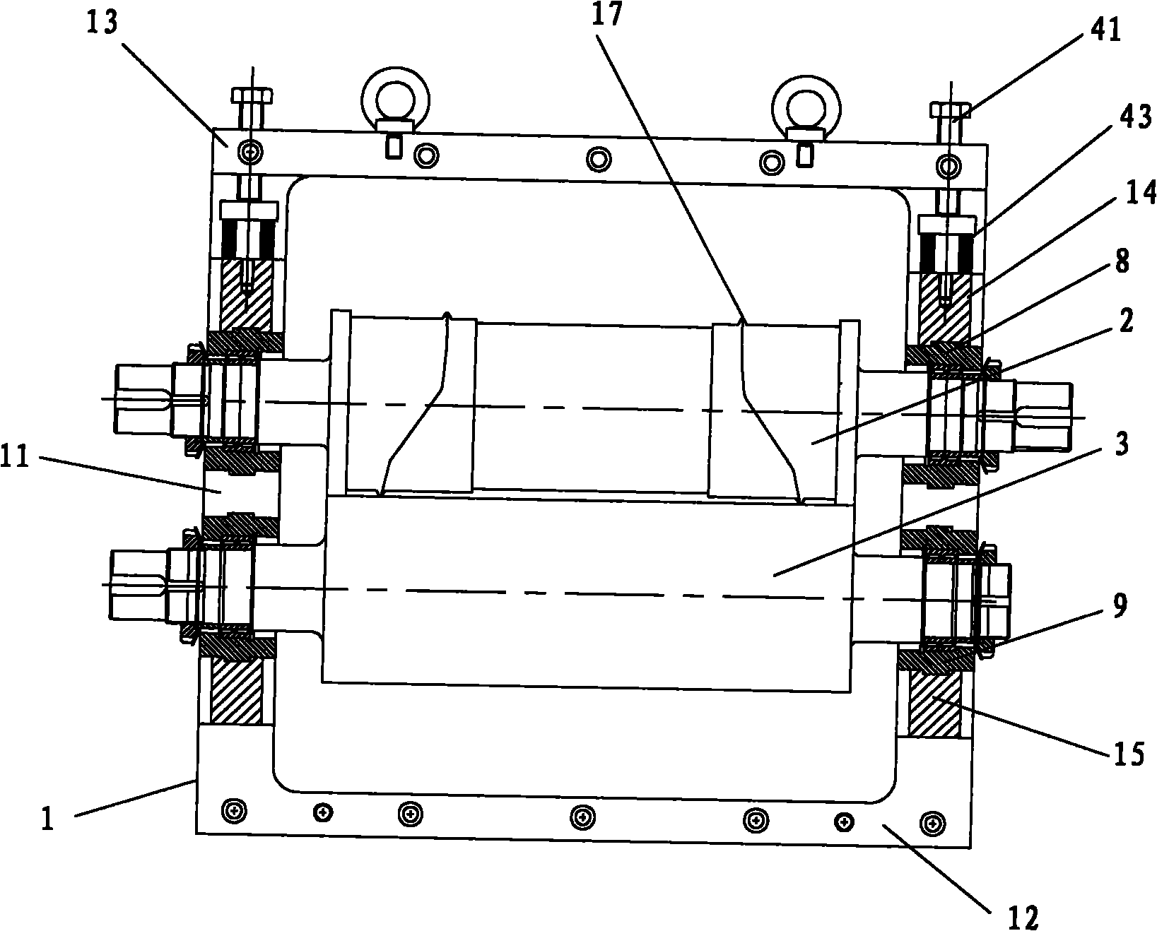
[0032] In order to describe the technical content, structural features, achieved goals and effects of the present invention in detail, the following will be described in detail in conjunction with the embodiments and accompanying drawings.

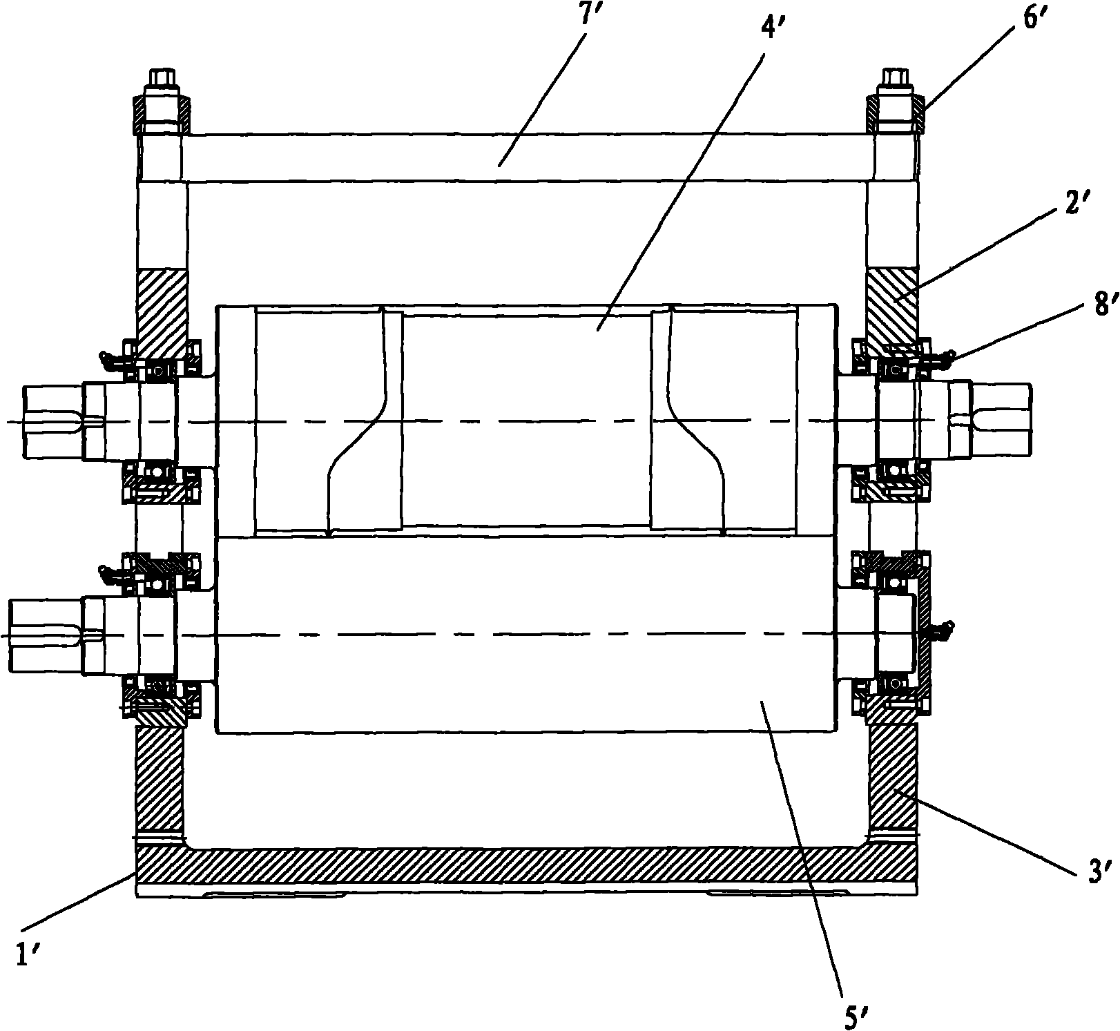
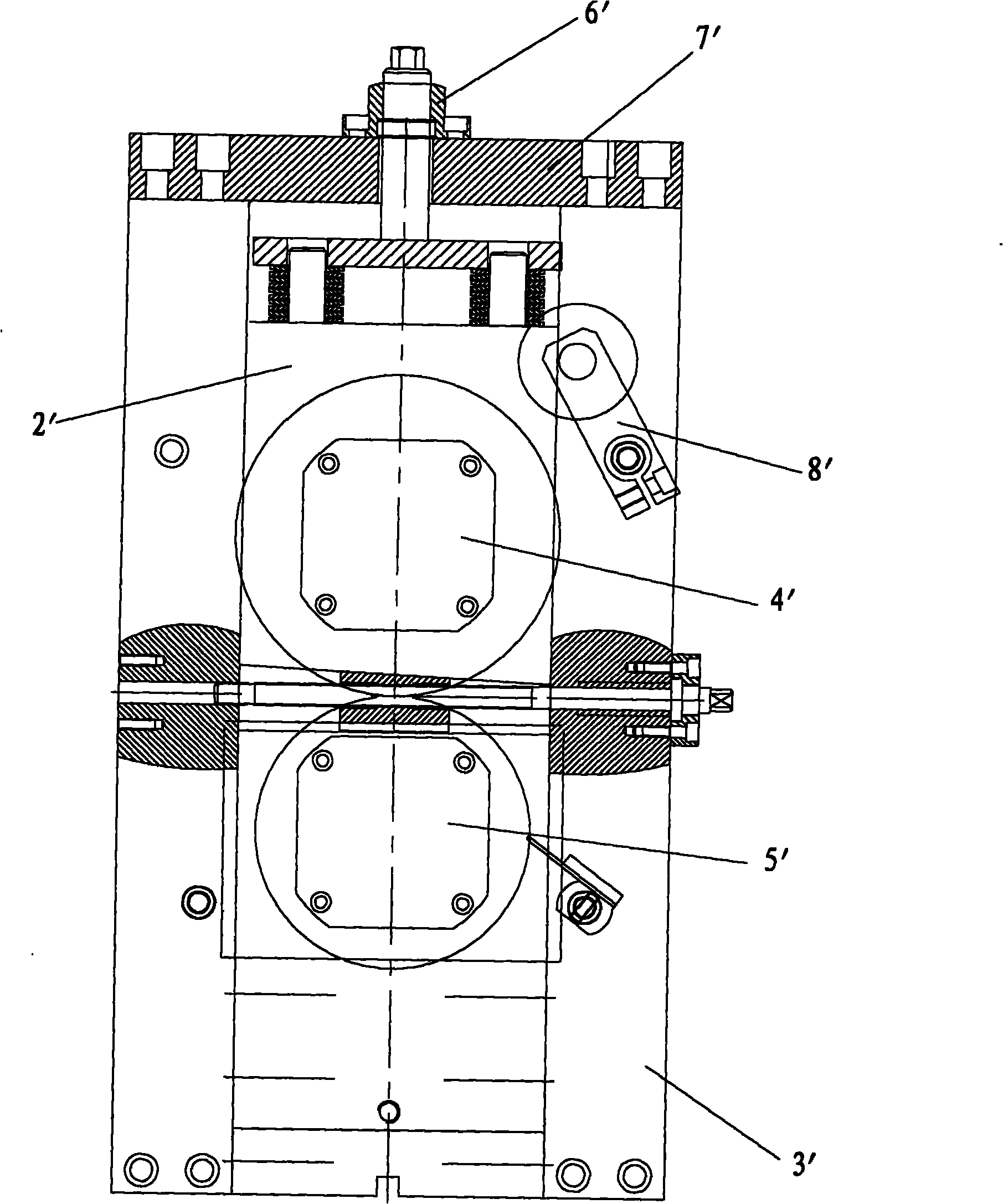
[0033] Please refer to Figure 3 to Figure 8 As shown, the present invention discloses a rotary die-cutting device, which includes a frame body 1, an upper knife roller 2 and a lower knife roller 3 fixed on the frame body 1, and two ends respectively installed on the upper knife roller 2 and the lower knife roller 3. The upper bearing sleeve 8 and the lower bearing sleeve 9 and the upper slider 14 and the lower slider 15 connected with the upper bearing sleeve 8 and the lower bearing sleeve 9 respectively, wherein: including a pressurization mechanism 4 and a pressure relief mechanism 5, the pressurization The mechanism 4 cooperates with the upper bearing sleeve 8 through the upper slider 14, and the pressing mechanism 4 exerts a downward ...


PUM


Abstract

The invention discloses a rotating die cutting device, comprising a frame body, an upper knife roll and a lower knife roll fixed on the frame body, an upper bearing sleeve and a lower bearing sleeve respectively installed on two ends of the upper knife roll and the lower knife roll, and an upper slide block and a lower slide block respectively connected with the upper bearing sleeve and the lower bearing sleeve, wherein the rotating die cutting device further comprises a pressurizing mechanism and a pressure release mechanism; the pressurizing mechanism is matched with the upper bearing sleeve through the upper slide block; the pressurizing mechanism applies a downward force to the upper knife roll; the pressure release mechanism comprises a pressure release rod and a first elastic piece; the first elastic piece is installed on the pressure release rod; the pressure release rod is connected with the upper slide block or the lower slide block; and the first elastic piece applies an upward force to the upper knife roll by the pressure release rod. The distance between the upper knife roll and the lower knife roll is conveniently adjusted by the coordination of the pressurizing mechanism and the pressure release mechanism; in actual using process, the rotating die cutting device is quick to detach and high in repeated mounting precision without detaching the bearing sleeves when the knife rolls are grinded again; the rotating die cutting device is not only beneficial for keeping the precisions of knife rolls, and simultaneously the mounting efficiency is also largely increased.

Description

technical field [0001] The invention relates to the field of mechanical technology, in particular to a rotary die-cutting device. Background technique [0002] At present, the application of rotary die-cutting technology at home and abroad is becoming more and more extensive. The industry involves non-woven fabrics, household paper, various packaging, printing, self-adhesive trademark labels, medical dressings, plastic products, leather products, daily necessities, electronic products, Batteries, metal foils, PE and PP films, etc. [0003] Please refer to figure 1 and figure 2 Shown is a schematic structural view of a prior art rotary die-cutting device. The rotary die-cutting device is a column structure, including four columns 1', the upper bearing block slider 2', the lower bearing block slider 3' are fixed together with the upper knife roller 4' and the lower knife roller 5' respectively , The pressurizing mechanism 6' is set on the top plate 7', and there is a wedg...

Claims


Application Information

Patent Timeline
IPC IPC(8): B26D7/26
Inventor 郭尚接
Owner 三明市普诺维机械有限公司
Why Eureka
Try Eureka