
Chip module structure assembly

A chip module and assembly technology, applied in the field of chip module structure assembly, can solve problems such as easy heat storage, difficult heat dissipation, and inability to load heat energy

Inactive Publication Date: 2010-07-07
TAIWAN ELECTRONICS PACKAGING
View PDF0 Cites 3 Cited by
  • Summary
  • Abstract
  • Description
  • Claims
  • Application Information

AI Technical Summary

Problems solved by technology

However, when the chip module structure assembly 1 is electrically connected to an interface above USB 2.0, since USB 2.0 is a high-frequency signal transmission, the high-frequency signal will further increase the heat generated by the chip 3; in other words, the chip 3 cannot load The heat energy generated during operation leads to the problem of overheating and noise generation
[0004] In order to solve the above problems, in the prior art, the chip 3 is attached to the substrate to dissipate heat through the substrate 2; however, since the substrate 2 is generally made of glass fiber material, this material is not easy to dissipate heat and is easy to store heat; in other words , as far as the prior art chip module structure assembly 1 is concerned, it has the disadvantage of poor heat dissipation effect

Method used


Image

  • Chip module structure assembly
  • Chip module structure assembly
  • Chip module structure assembly

Examples


Embodiment Construction

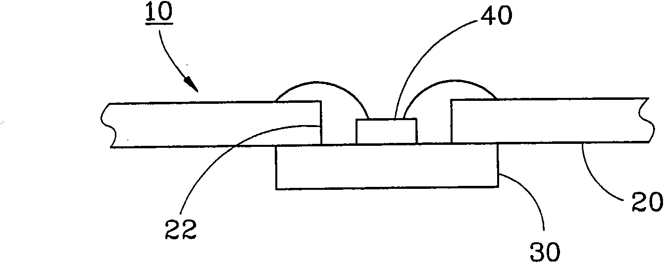
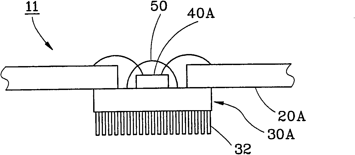
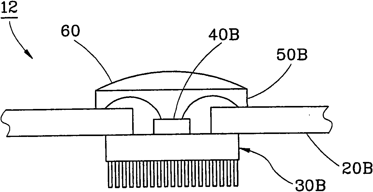
[0069] see figure 1 , The chip module structure assembly 10 provided by the first preferred embodiment of the present invention includes: a substrate 20 , a heat dissipation plate 30 , a chip 40 and a light-transmitting layer 50 .

[0070] The substrate 20 is flat and has a through hole 22; in this embodiment, the number of the through holes 22 corresponds to the number of the chips 40, and the number of the through holes 22 is taken as an example, which is only for illustration and not as a limiting requirement. .

[0071] The heat dissipation plate 30 is arranged on the bottom surface of the base plate 20, generally in the shape of a flat plate, and its position corresponds to the through hole 22; the thermal conductivity of the heat dissipation plate 30 is higher than that of the base plate 20; in this embodiment, the heat dissipation plate 30 is made of metal The material is only used as an example, not as a limiting requirement.

[0072] The chip 40 is disposed on the ...


PUM

PropertyMeasurementUnit
Angleaaaaaaaaaa
Angleaaaaaaaaaa

Abstract

The invention discloses a chip module structure assembly, which comprises a substrate, a heat dissipation plate and at least one chip, wherein the substrate is flat and is provided with a perforation; the heat dissipation plate is arranged on the bottom surface of the substrate, the position of the heat dissipation plate corresponds to the perforation, and the heat conduction coefficient of the heat dissipation plate is higher than that of the substrate; and the at least one chip is arranged on the top surface of the heat dissipation plate and corresponds to the perforation, and the chip is electrically connected with the substrate. Through the structure, the chip module structure assembly can quickly conduct the heat to the outside. Compared with the prior art, the chip module structure assembly has the characteristic of better heat dissipation effect.

Description

technical field [0001] The invention relates to a chip module, in particular to a chip module structure assembly. Background technique [0002] see Figure 11 , the prior art chip module structure assembly 1 has a substrate 2 and a chip 3 disposed on the substrate 2 . [0003] However, since there are many types of the chip 3, for example, high-frequency chips such as LED chips or CMOS chips are designers; for LED chips, better heat dissipation effects are needed to prolong the service life; For a CMOS chip, when the chip module assembly 1 is electrically connected to the USB 1.0 interface, since the USB 1.0 is still a low-frequency signal transmission, the chip 3 can still bear the heat generated during operation. However, when the chip module structure assembly 1 is electrically connected to an interface above USB 2.0, since USB 2.0 is a high-frequency signal transmission, the high-frequency signal will further increase the heat generated by the chip 3; in other words, th...

Claims


Application Information

Patent Timeline
IPC IPC(8): H01L23/367H01L23/488H01L25/00
CPCH01L2224/8592H01L2924/181H01L2224/48091H01L2224/48137H01L2924/00014H01L2924/00012
Inventor 吴澄郊
Owner TAIWAN ELECTRONICS PACKAGING
Learn More