
Fluid distribution method for rapid-cooling heat exchanger

A quenching heat exchanger and fluid distribution technology, applied in the direction of heat exchanger shell, fluid circulation arrangement, refrigerator, etc., can solve the problems of long residence time, uncontrollable adiabatic residence time, etc., to improve the utilization rate and slow down the rising rate. , Improve the effect of operating cycle

Active Publication Date: 2012-12-12
CHINA PETROLEUM & CHEM CORP +1
View PDF2 Cites 0 Cited by
  • Summary
  • Abstract
  • Description
  • Claims
  • Application Information

AI Technical Summary

Problems solved by technology

[0005] In order to improve the design of the cracked gas inlet channel of the traditional quenching heat exchanger, improve the flow distribution of the cracked gas, overcome the shortcoming of the cracked gas staying at high temperature for a long time due to the back-mixing of the inlet gas flow, and reduce the uncontrollable adiabatic residence time caused by backflow , foreign developers of quenching heat exchangers have made improvements at the entrance

Method used


Image

  • Fluid distribution method for rapid-cooling heat exchanger
  • Fluid distribution method for rapid-cooling heat exchanger
  • Fluid distribution method for rapid-cooling heat exchanger

Examples


Embodiment Construction

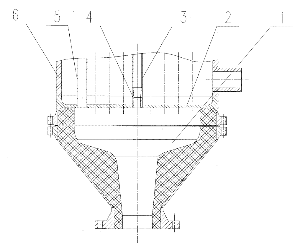
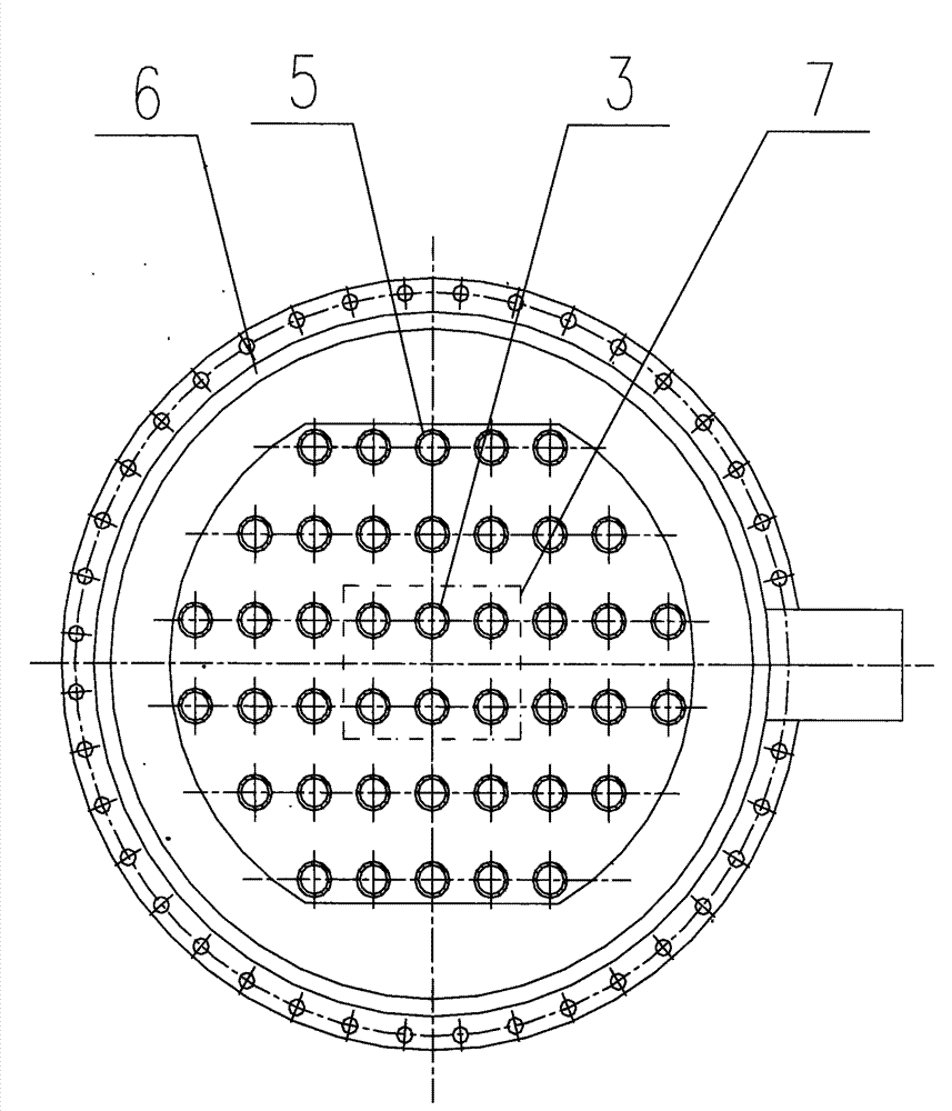
[0021] refer to Figure 1 ~ Figure 3 , a fluid distribution system of a quenching heat exchanger includes a quenching heat exchanger inlet channel 1, an inlet tube plate 2, a central heat exchange tube 3, a short flow equalizing tube 4, surrounding heat exchange tubes 5, a cylinder 6 and other components. The central heat exchange tube 3 is composed of two tubes, the entrance is a short flow equalizing tube 4, and the exit is a section of equal diameter tube. The two are butt welded to form a complete central heat exchange tube 3 after welding. The inner diameter of the short flow equalizing tube 4 is smaller than the inner diameter of the equal-diameter tube of the central heat exchange tube 3 , and the inner diameter of the equal-diameter tube at the outlet of the central heat exchange tube 3 is the same as that of the surrounding heat exchange tubes 5 .

[0022] The following specific examples were simulated and calculated by computational fluid dynamics (CFD). There are 42...


PUM


Abstract

The invention relates to a fluid distribution system for a rapid-cooling heat exchanger. Heat exchange tubes of the rapid-cooling heat exchanger comprise a center heat exchange tube (3) and a periphery heat exchange tube (5), the entrance end of the center heat exchange tube (3) is a short uniform-flow tube (4), the exit end of the center heat exchange tube (3) is an equal-diameter tube, the short uniform-flow tube (4) and the equal-diameter tube are butt-welded, so as to form the whole center heat exchange tube (3), and the periphery heat exchange tube (5) is an equal-diameter tube, the inner diameter of the inner tube of which is invariable in the full-length range. By adopting the method, the flow resistance property of the center heat exchange tube (3) is adjusted to lead the flow resistance of the center heat exchange tube (3) to increase properly, thus reducing the cracking gas flow in the center heat exchange tube (3) and increasing the cracking gas flow in the periphery heat exchange tube (5), so as to lead the fluid to distribute uniformly. The rapid-cooling heat exchanger which is provided with a fluid distribution system can distribute the cracking gas into each heat exchange tube uniformly, thus improving the utilization ratio of the heat exchange tubes and prolonging the running period.

Description

technical field [0001] The invention relates to equipment used in ethylene cracking technology, in particular to a fluid distribution system of a quenching heat exchanger. Background technique [0002] After the pyrolysis raw material is cracked at high temperature in the furnace tube of the cracking furnace, ethylene is generated, and important by-products such as propylene, butadiene, benzene, toluene, and xylene are obtained at the same time. The high-temperature cracked gas at the outlet of the cracking furnace will continue to carry out the cracking reaction (secondary reaction) under the high-temperature condition of the outlet. If the residence time is too long, the secondary reaction will increase. As a result, the yield of olefins in the cracked product will decrease, and methane, hydrogen, Heavy tar increases, and the tendency of coking increases. To keep the yield of ethylene stable and reduce the secondary reaction, the cracked gas must be cooled down as soon as...

Claims


Application Information

Patent Timeline
Patent Type & Authority Patents(China)
IPC IPC(8): F25B41/00F28F9/22C10G9/20
Inventor 李金科徐红兵康翼张建安发亮张贤福刘韫砚孙建兵毛小亮
Owner CHINA PETROLEUM & CHEM CORP
Learn More