Eureka AIR delivers breakthrough ideas for toughest innovation challenges, trusted by R&D personnel around the world.

Small pneumatic vehicle used in fire scene

A technology for on-site use and trolleys, which is applied in power units, vehicle parts, transportation and packaging, etc., which can solve problems such as high maintenance requirements, unfavorable popularization and application, and complex structures, and achieve easy maintenance, reduce its own weight, and protect personal safety. safe effect

Inactive Publication Date: 2010-06-30
WUHAN UNIV OF SCI & TECH
View PDF0 Cites 6 Cited by
  • Summary
  • Abstract
  • Description
  • Claims
  • Application Information

AI Technical Summary

Problems solved by technology

The main disadvantages of the method are: 1. It increases the labor intensity of firefighters, which makes them tired and reduces disaster relief efficiency and quality;
[0003] Although more mature highly integrated and highly intelligent fire-fighting robots have appeared, judging from the current usage, there are still some disadvantages: 1. It is driven by a motor, the vehicle-mounted power supply is bulky and the electrical control equipment increases its own weight, which is not suitable for High temperature, explosive and other disaster environments; 2. Expensive, complex structure, high maintenance requirements, not conducive to popularization and application

Method used


Image

  • Small pneumatic vehicle used in fire scene
  • Small pneumatic vehicle used in fire scene
  • Small pneumatic vehicle used in fire scene

Examples


Embodiment Construction

[0015] The present invention will be further described below in conjunction with specific embodiment: be not the limitation of its protection scope:

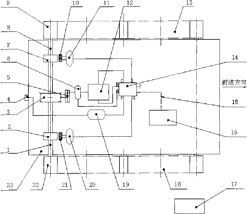
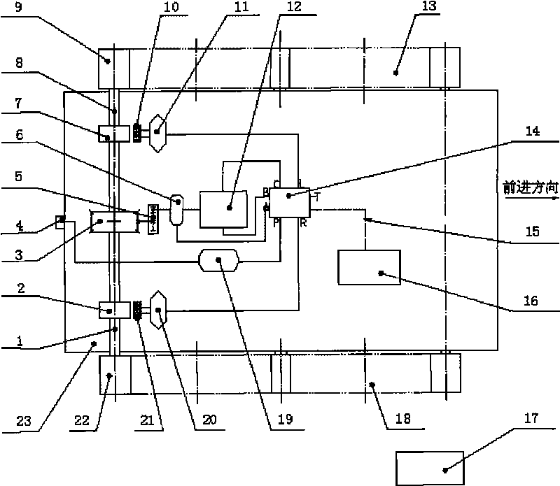
[0016] A pneumatic trolley for fire scene, its structure schematic diagram is as follows figure 1 and figure 2 As shown: the air source connector 4 of the trolley is installed at the tail of the vehicle body 23, one end of the air source connector 4 is externally connected to the high-pressure air source carried by the fire truck, and the other end of the air source connector 4 passes through the high-pressure air pipe and the accumulator 19 The outlet port of the accumulator 19 is connected to the valve port P of the solenoid valve block 14 through a high-pressure gas pipe; The valve port A of the solenoid valve block 14 is connected to the clutch 6 through a high-pressure air pipe; the valve port L of the solenoid valve block 14 is connected to the left brake cylinder 11 through a high-pressure air pipe, and the valve port R...


PUM


Abstract

The invention relates to a small pneumatic vehicle used in a fire scene, which has the technical scheme that an air source joint [4] arranged at the tail part of a vehicle body [23] is connected with a valve opening P of an electromagnetic valve block [14] through a high-pressure air pipe via an energy accumulator [19], a valve opening B and a valve opening C of the electromagnetic valve block [14] are respectively connected with two air holes of a pneumatic motor [12] through high-pressure air pipes, the valve opening A of the electromagnetic valve block [14] is connected with a clutch [6] through a high-pressure air pipe, a valve opening L and a valve opening R of the electromagnetic valve block [14] are respectively connected with a left braking air cylinder [11] and a right braking air cylinder [20] through high-pressure gas pipes, the pneumatic motor [12] respectively drives a left side driving shaft [8] and a right side driving shaft [1] of the small vehicle through the clutch [6], a speed reducer [5] and a differential mechanism [3], a remote controller [17] is in wireless connection with a signal receiving and control module [16], and the signal receiving and control module [16] is connected with the electromagnetic valve block [14] through a cable [15]. The invention has the characteristics that the small pneumatic vehicle is applicable to the dangerous environment such as high-temperature environment, the explosive environment and the like, and the safety of firefighters can be ensured.

Description

technical field [0001] The invention belongs to the technical field of pneumatic trolleys. Specifically relates to a pneumatic trolley for fire scene. Background technique [0002] At present, the transfer of materials and equipment at the fire scene is mostly realized by the manpower of firefighters, so firefighters must often enter and exit the fire scene. The main disadvantages of the method are: 1. It increases the labor intensity of firefighters, which makes them tired and reduces disaster relief efficiency and quality; . [0003] Although more mature highly integrated and highly intelligent fire-fighting robots have appeared, judging from the current usage, there are still some disadvantages: 1. It is driven by a motor, the vehicle-mounted power supply is bulky and the electrical control equipment increases its own weight, which is not suitable for High temperature, explosive and other disaster environments; Second, the price is expensive, the structure is complicat...

Claims


Application Information

Patent Timeline
Patent Type & Authority Applications(China)
IPC IPC(8): B60K8/00
Inventor 王兴东孔建益陈江艳高全杰冒颖和毅吴洋子
Owner WUHAN UNIV OF SCI & TECH
Why Eureka
Eureka Blog
Learn More