Underwater remote-control welding system

An underwater remote control and welding system technology, applied in welding equipment, welding accessories, arc welding equipment and other directions, can solve the problems of high labor input cost and the underwater remote control welding system has not yet appeared, which is conducive to the elimination of welding fumes and improved performance. The effect of the clarity of the camera and the simplified sealing design

Inactive Publication Date: 2010-06-30
BEIJING INSTITUTE OF PETROCHEMICAL TECHNOLOGY +1
View PDF7 Cites 11 Cited by
  • Summary
  • Abstract
  • Description
  • Claims
  • Application Information

AI Technical Summary

Problems solved by technology

Although robots are used in the maintenance of many other nuclear power equipment, a mature and practical underwater remote control welding system has not yet appeared. At present, manual welding is performed by diving welders wearing heavy professional protective clothing
Submersible welders weld by hand and are directly exposed to the radiation environment. Moreover, because the power station cannot accept the cooling downtime cost of up to 500,000 US dollars per hour, the water temperature inside some containers is very high, and the working environment is extremely harsh. The working time of a welder usually does not exceed 1 hour, in addition, personnel are required to monitor the radiation dose received by diving welders on the surface of the water, so the cost of manpower input is high

Method used


Image

  • Underwater remote-control welding system
  • Underwater remote-control welding system

Examples


Embodiment Construction

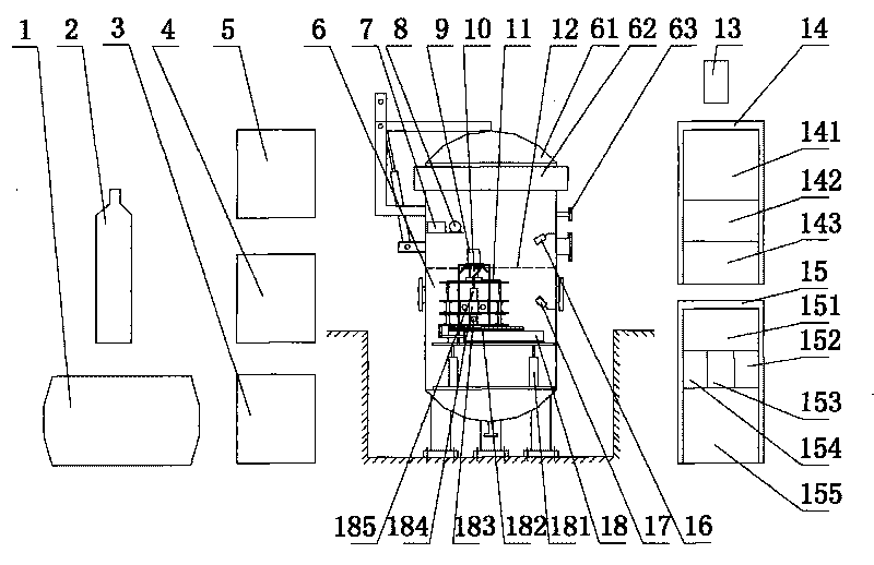
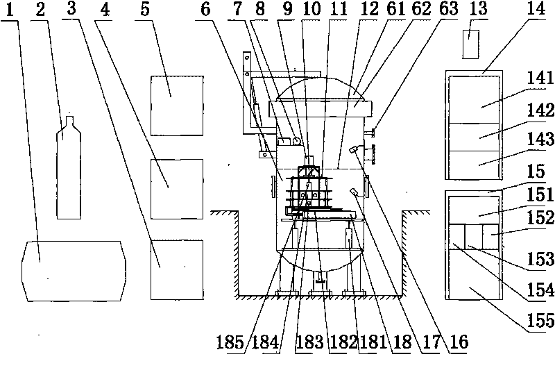
[0021] Depend on figure 1 It shows an underwater remote control welding system, which mainly consists of air compressor 1, Ar gas cylinder 2, test chamber hydraulic station 3, welding power supply 4, welding platform hydraulic station 5, underwater welding test chamber 6, welding platform valve group 7. Wire feeder 8, underwater welding camera 9, drainage air cover 10, test steel plate 11, water surface 12, welding manual control box 13, control system cabinet 14, monitoring TV cabinet 15, water surface camera 16, underwater camera 17 and The welding platform 18 consists of: the underwater welding test chamber 6 is filled with water to the water surface 12, the welding platform valve group 7, the wire feeder 8, the underwater welding camera 9, the drainage air cover 10, the test steel plate 11, the water surface camera 16, the water surface The lower camera 17 and the welding platform 18 are installed in the underwater welding test cabin 6, the air compressor 1, the Ar gas cyl...


PUM


Abstract

The invention discloses an underwater remote-control welding system, which is composed of an air compressor (1), an Ar gas bottle (2), a test chamber hydraulic station (3), a welding power supply (4), a welding platform hydraulic station (5), an underwater welding test chamber (6), a welding platform valve group (7), a wire feeder (8), an underwater welding camera (9), a drainage gas mask (10), a test steel plate (11), a water surface (12), a welding manual box (13), a control system cabinet (14), a monitor TV cabinet (15), a water surface camera (16), an underwater video camera (17) and a welding platform (18); wherein the underwater welding test chamber (6), the welding platform valve group (7), the wire feeder (8), the underwater welding camera (9), the drainage gas mask (10), the test steel plate (11), the water surface camera (16), the underwater video camera (17) and the welding platform (18) are arranged in the underwater welding test chamber (6); the air compressor (1), the Ar gas bottle (2), the test chamber hydraulic station (3), the welding power supply (4), the welding platform hydraulic station (5), the welding manual box (13), the control system cabinet (14) and the monitor TV cabinet (15) are positioned outside the underwater welding test chamber (6) and connected to the internal equipment of the underwater welding test chamber (6) through cables and air tubes. The invention can be used for the situation which staff cannot enter into such as deep water and the radiation environment, has compact equipment composition and high overall reliability, reduces operational risk, reduces labor intensity and improves production efficiency.

Description

technical field [0001] The invention relates to underwater welding experiment research equipment, in particular to an underwater remote control welding combination equipment. Background technique [0002] There are many radioactive containers in nuclear power plants, such as reactor pressure vessels, evaporators, pressurizers, condensers, spent fuel pools, refueling pools, feed water pools, etc. Due to nuclear radiation stress and other effects, radioactive containers are prone to corrosion cracks and surface abrasions that seriously threaten the safe operation of the power station. Welding repairs such as leak repair welding, crack opening groove repair welding, and wear and corrosion surface overlay welding are required. To reduce repair costs and radiation effects, welding is performed in water. Although robots are used in the maintenance of many other nuclear power equipment, a mature and practical underwater remote control welding system has not yet appeared. Currently...

Claims


Application Information

Patent Timeline
IPC IPC(8): B23K9/16B23K9/10B23K9/32
Inventor 焦向东周灿丰沈秋平余燕张俊宝顾国兴陈煜高辉朱加雷刘德华
Owner BEIJING INSTITUTE OF PETROCHEMICAL TECHNOLOGY
Why Eureka
Try Eureka