
LED lamp lighting method with high effective exposure rate

A technology of LED lamps and irradiance rate, which is applied in the field of lighting, and can solve the problems of no industrial applicability, edge luminosity not meeting requirements, and inability to realize rectangular illumination of roads, etc.

Inactive Publication Date: 2010-06-23
欧阳杰 +1
View PDF4 Cites 12 Cited by
  • Summary
  • Abstract
  • Description
  • Claims
  • Application Information

AI Technical Summary

Problems solved by technology

This solution solves part of the waste of light effect, but the brightness ratio between the center and both ends of the spot reaches 4:1, and the luminosity of the edge does not meet the requirements, especially in foggy or rainy days, the brightness of the edge may be less or even dark
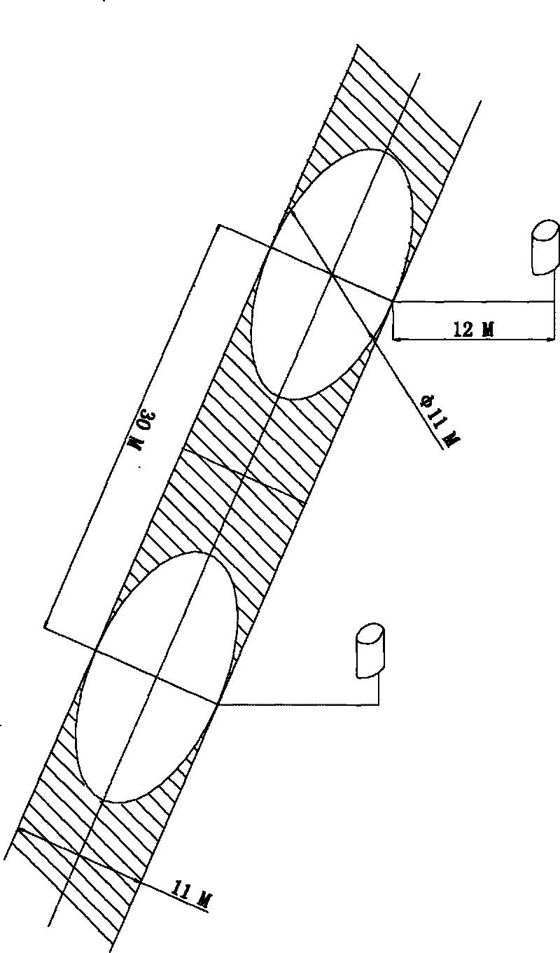
[0008] Chinese patent CN1995808 split type LED projection lighting method discloses an LED street lamp, the solution is to determine the irradiated surface and the number of high-power light-emitting diode lamps; set high-power light-emitting diode lamps; configure projection lens groups; wherein the irradiated surface can be illuminated Divided into adjacent and regularly distributed illuminated surface units, the number of illuminated surface units is the same as the number of high-power LED lamps; the luminous flux of the area of ​​the illuminated unit * projection lens transmittance / illuminated surface requirements The average illuminance; but this patent does not take into account that the street lamp is set on a 12-high light pole, and the light from the LED to the ground needs to pass a distance of 12m to 22m, and the effective luminous flux of a single pixel point on the surface of the illuminated object at the actual receiving end = (total luminous flux of the LED corresponding to the emitting end × heat attenuation factor × lens quenching rate + afterglow) × transmittance × distance loss factor, so the brightness is much smaller than the 15Lux described in the patent, so the number of lights is obvious It cannot be set as described in the patent, so it has no industrial applicability. In addition, as shown in the accompanying drawings of the patent Image 6 As shown, its peripheral LEDs are arranged in a ring shape, so its illumination surface on the ground can only be circular or oval, and it is impossible to achieve rectangular illumination of the road.
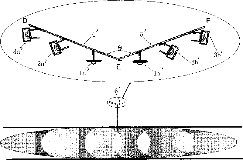
[0010] The lens arrangement of this patent is similar to the V arrangement of CREE except that the form is changed to an inverted V shape (same as the hourglass shape of patent 200720005613. Will have the same problem as CREE street lights

Method used


Image

  • LED lamp lighting method with high effective exposure rate
  • LED lamp lighting method with high effective exposure rate
  • LED lamp lighting method with high effective exposure rate

Examples


Embodiment Construction

[0032] The invention will be described in detail below in conjunction with the accompanying drawings.

[0033] like Figure 8 , Figure 10 As shown, the irradiated surface is evenly divided, so that each LED corresponds to an independent irradiated area on the road, because each LED is only responsible for a small lighting area, so only the LEDs responsible for the edge area will have a waste of light source, such as Figure 11 Shown: For a rectangular illuminated surface with length L and width W, divide it into n equal parts with side length a×a, and the circle Φb with b as the diameter is the pixel on the illuminated surface required by our single LED plus lens point. The irradiation areas are normal irradiation area, overlapping irradiation area (overlapping area of ​​two adjacent light spots), outer area (located outside the required irradiation area -> light damage area, but as shown in the figure, the range of this area is very small, basically Negligible, the area o...


PUM


Abstract

The invention discloses an LED lamp lighting method with a high effective exposure rate. In the lighting method, a plurality of LEDs which are assigned in a dome camber array are arranged in an LED lamp lighting device, and the front of each LED is provided with a lens device, so each LED is corresponding to an independent exposure area on an exposed surface, and all exposure areas are covered with exposure surfaces; as each lighting unit (pixel )on an area to be exposed is covered by light spots formed by the corresponding LED, an dead angle of exposure does not exist, and the brightness of the entire exposed face is very uniform; at the same time, all LEDs are exposed on the corresponding area, and the effective exposure rate of a lamp is very high, so light pollution can not be generated, and a waste of light effect can not exist.

Description

technical field [0001] The invention relates to an illuminating method, especially an illuminating method using LED as a light source with high effective irradiance rate. Background technique [0002] In recent years, as the luminous efficiency of LED has increased by 100 times and the cost has dropped by 10 times, its development prospects in the lighting field have attracted global lighting manufacturers to join in LED light source and market development. The United States, Japan, Europe and Taiwan Province of China have all launched semiconductor lighting programs. In 2001, my country's 863 plan was established, and in 2003, the "National Semiconductor Lighting Project" was launched urgently. Starting from the "Eleventh Five-Year Plan" in 2006, the country will promote the semiconductor lighting project as a major project. At present, my country's economy is growing rapidly, and the contradiction of energy shortage is becoming more and more obvious. The electric energy ...

Claims


Application Information

Patent Timeline
Patent Type & Authority Applications(China)
IPC IPC(8): F21S8/00F21V19/00F21V5/04F21Y101/02F21W131/103
Inventor 欧阳杰欧阳伟
Owner 欧阳杰
Learn More