Device for rapidly collecting and releasing boats
A technology for retracting devices and small boats, which is applied in hoisting devices, transportation and packaging, and load hanging components, etc., and can solve problems such as reducing the normal service life of the sling, collision between the small boat and the mother ship, and danger
- Summary
- Abstract
- Description
- Claims
- Application Information
AI Technical Summary
Problems solved by technology
Method used
Image
Examples
Embodiment 1
[0106]
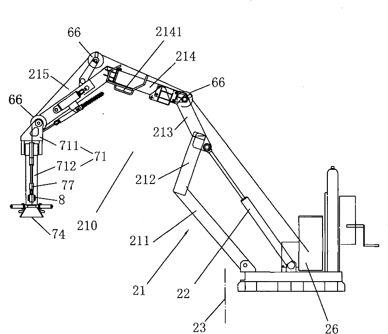
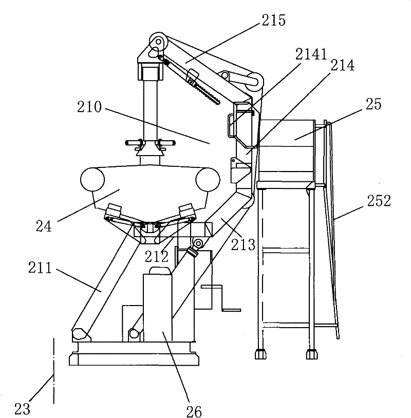
[0107] Such as figure 1 , figure 2As shown, it is a structural schematic diagram of a built-in boat quick retractable device provided by the present invention under two states of unfolding and retracting, and its specific structure will be explained one by one in the following text:
[0108] (1) retractable arm structure: it includes a boom 21 and a luffing cylinder 22, one end of the boom 21 is pivotally connected to the mother ship (not shown), and the other end is an overhanging end, the luffing cylinder 22 One end is pivotally connected to the mother ship, and the other end is pivotally connected to the boom 21 to control the expansion and retraction of the boom 21; wherein: the overhanging end of the boom 21 is bent into a concave shape, and the concave suspension The extension end 21 has an opening 210 towards the outside of the side 23 of the mother ship.
[0109] When luffing oil cylinder 22 elongates, as figure 1 As shown, the jib 21 will be launched, a...
Embodiment 2
[0172]
[0173] It is that: the structure form of retractable arm structure has bigger difference.
[0174] (1) retractable arm structure: it is the main difference with embodiment 1.
[0175] Such as Figure 22 , Figure 23 Shown, the present invention has adopted a kind of open retractable arm structure, and it comprises:
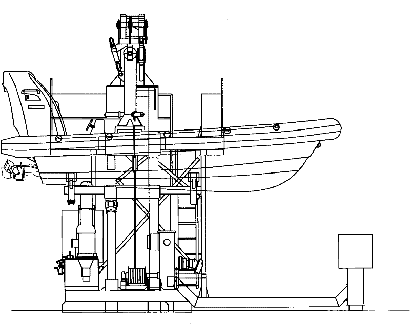
[0176] Rotary mechanism 11, such as image 3 As shown, it consists of a base 111, a slewing bearing 112, a slewing tower body 113 and a driving mechanism 114. The base 111 is fixed on the deck of the mother ship, and the slewing tower body 113 is pivotally connected to the base 111 through the slewing bearing 112. The driving mechanism 114 drives the slewing tower body 113 to rotate around the base 111 . In this embodiment, the drive mechanism 114 is a hydraulic drive motor fixed on the slewing tower body 113, and an external gear (not shown) is connected to the output shaft of the hydraulic drive motor. There is an internal gear (not shown in the ...
PUM
 Abstract
Description
Claims
Application Information
 - R&D
- Intellectual Property
- Life Sciences
- Materials
- Tech Scout
- Unparalleled Data Quality
- Higher Quality Content
- 60% Fewer Hallucinations
Browse by: Latest US Patents, China's latest patents, Technical Efficacy Thesaurus, Application Domain, Technology Topic, Popular Technical Reports.
© 2025 PatSnap. All rights reserved.Legal|Privacy policy|Modern Slavery Act Transparency Statement|Sitemap|About US| Contact US: help@patsnap.com


