
A power line deicing device

A transmission line and pair technology, applied in the field of transmission line maintenance devices, can solve the problems of energy consumption, system safety impact, high cost, etc., and achieve the effects of low deicing cost, good safety performance and high efficiency

Active Publication Date: 2012-02-15
GUANGDONG KEYSTAR INTELLIGENCE ROBOT CO LTD
View PDF1 Cites 0 Cited by
  • Summary
  • Abstract
  • Description
  • Claims
  • Application Information

AI Technical Summary

Problems solved by technology

[0002] Over the years, especially in 2008, the overhead transmission lines in many places were covered with ice due to freezing rain in winter and spring, and lead (ground) wires were broken, hardware and towers were damaged due to conductor galloping. Even accidents such as collapses cause large-scale power outages, cause heavy losses, and seriously threaten the safe and stable operation of the power grid.
[0003] At present, most of the deicing work on transmission lines in China still adopts manual deicing methods, such as tapping with sticks or shooting with rifles, etc., which requires more personnel and resource input and cannot achieve the required efficiency. , and it is difficult to guarantee the life safety of deicing personnel
Or use the high-voltage line to melt ice, but high-voltage line ice-melting consumes too much energy, and the energy consumption of mechanical de-icing is much less than that of high-current ice-melting
The high-current ice-melting method is more efficient, but it is costly and complicated to operate, which has a great impact on system safety

Method used


Image

  • A power line deicing device
  • A power line deicing device
  • A power line deicing device

Examples


Embodiment Construction

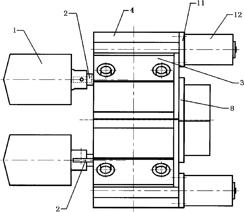
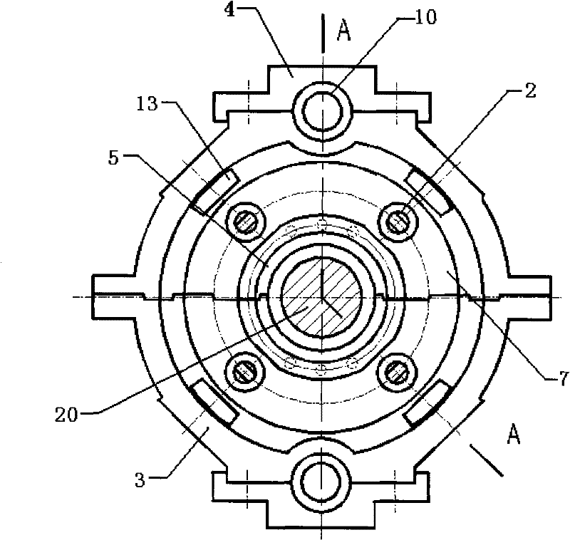
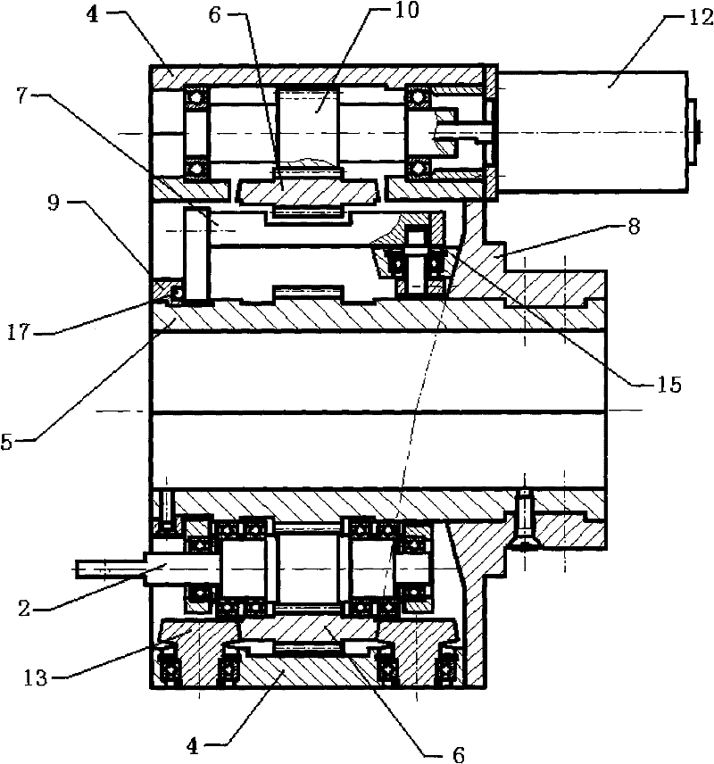
[0022] Figure 1. Milling cutter. 2. Planetary gear shaft. 3. Shell. 4. Shell cover. 5. Sun wheel. 6. External gear. 7. Cage. 8. Back cover. 9. Baffle. 10. Motor gear shaft. 11. Cover plate. 12. Drive motor. 13. External gear roller. 15. Cage rollers. 16. Locating pins. 17 balls. 18 connection plates. 19 Robots walking along transmission lines. 20. Power lines.

[0023] combine Figure 1~1 0 The present invention will be further described below in conjunction with embodiment.

[0024] The present invention relates to a power transmission line maintenance device, especially a power transmission line deicing device, which includes a sun gear 5 fastened on the power transmission line 20, a casing 3 arranged outside the sun gear 5 and having an "O"-shaped inner wall, The cage 7 arranged along the circumference of the outer wall of the sun gear 5, the casing cover 4 connected to the top and bottom of the casing 3, the driving motor 12 and the reducer are characteri...


PUM


Abstract

The invention provides a deicing device that can be directly installed or configured on an existing line patrol robot, and can directly transform the line patrol robot into a deicing robot for a high-voltage transmission line. The invention adopts a milling cutter for deicing, and the milling cutter is fixed on the planetary gear shaft, and the planetary gear shaft rotates around the sun gear while the planetary gear shaft rotates in the transmission of the planetary gear, so as to realize the rotating deicing of the transmission line. The invention has the advantages that it not only has good deicing effect, but also has high efficiency and high safety.

Description

technical field [0001] The invention relates to a power transmission line maintenance device, in particular to a power transmission line deicing device. Background technique [0002] Over the years, especially in 2008, the overhead transmission lines in many places were covered with ice due to freezing rain in winter and spring, and lead (ground) wires were broken, hardware and towers were damaged due to conductor galloping. Even accidents such as collapses cause large-scale power outages, causing heavy losses and seriously threatening the safe and stable operation of the power grid. [0003] At present, most of the deicing work on transmission lines in China still adopts manual deicing methods, such as tapping with sticks or shooting with rifles, etc., which requires more personnel and resource input and cannot achieve the required efficiency. , It is also difficult to guarantee the life safety of deicing personnel. Or use the method of melting ice with high-voltage lines...

Claims


Application Information

Patent Timeline
Patent Type & Authority Patents(China)
IPC IPC(8): H02G7/16F16H1/28
Inventor 吴功平肖华李莹松白玉成严宇
Owner GUANGDONG KEYSTAR INTELLIGENCE ROBOT CO LTD
Learn More