Method for detecting contacts, and touch panel using same

A touch panel and detection method technology, applied in the input/output process of data processing, instruments, electrical digital data processing, etc., can solve the problem that the output voltage changes, the touch panel cannot realize multi-point detection, and the controller cannot correctly Determine the position of the contact point and other issues to avoid misjudgment

Active Publication Date: 2010-06-16
ORISE TECH CO LTD
View PDF3 Cites 11 Cited by
  • Summary
  • Abstract
  • Description
  • Claims
  • Application Information

AI Technical Summary

Problems solved by technology

[0006] However, it can be known from the above operations that when the area A and the area B are simultaneously touched and subjected to pressure, the output voltages of the comparators AMP1_1, AMP2_4, AMP1_3, and AMP2_1 will all change.
Therefore, the controller of the touch panel may determine that the contact point is in area A and area B, but may also determine that the contact point is in area C and area D, so that the controller cannot correctly determine the position of the contact point
Therefore, due to the limitation of circuit design, the above-mentioned touch panel cannot realize the technology of multi-point detection.

Method used


Image

  • Method for detecting contacts, and touch panel using same
  • Method for detecting contacts, and touch panel using same
  • Method for detecting contacts, and touch panel using same

Examples


Embodiment Construction

[0040] In order to make the above and other objects, features and advantages of the present invention more comprehensible, preferred embodiments will be described in detail below together with the accompanying drawings.

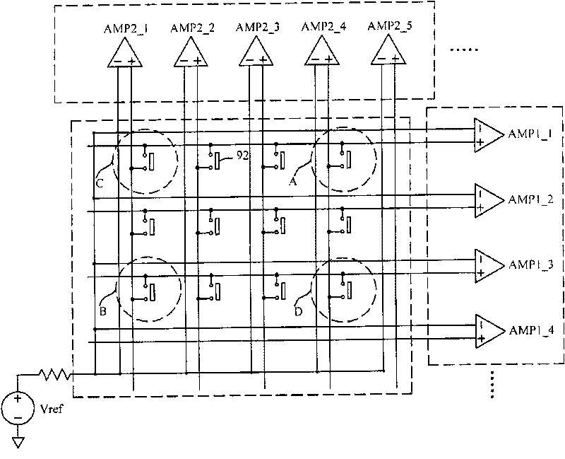
[0041] Figure 4 It is a system block diagram of a touch panel according to an embodiment of the present invention. Please refer to Figure 4 , the touch panel includes a resistive pressure sensing matrix 410 , a sequential scanning driver 420 and M X-axis sensing circuits 430 . The resistive pressure sensing matrix 410 includes M X-axis sensing lines and N Y-axis sensing lines. For the convenience of describing this embodiment, it is assumed in this example that the resistive pressure sensing matrix 410 includes five X-axis sensing lines LX1 - LX5 and four Y-axis sensing lines LY1 - LY5 .

[0042] When the user uses tools such as a stylus or fingers to exert pressure on the touch panel, some blocks of the resistive pressure sensing matrix 410 will be pres...


PUM


Abstract

The invention relates to a method for detecting contacts, and a touch panel using the same. The method is suitable for detecting a plurality of contacts and comprises the following steps of: providing a resistance type pressure sensing matrix, wherein the resistance type matrix comprises M X-axis induction lines and N Y-axis induction lines, and when a preset range of the junction between the ith X-axis induction line and the jth Y-axis induction line receives a pressure, the ith X-axis induction line and the jth Y-axis induction line are short-circuited; supplying a scanning voltage to the pth Y-axis induction line in a pth scanning period; detecting the M X-axis induction lines to judge whether any scanning voltage is detected; and determining the touched coordinate to be (q, p) when the qth X-axis induction line receives the scanning voltage in the pth scanning period, wherein M, N, i, p and q are positive integers, i is more than 0, q is less than or equal to M, and p is more than 0 and less than or equal to N.

Description

technical field [0001] The present invention relates to a touch panel technology, and in particular to a touch point detection method and a touch panel using the touch point detection method. Background technique [0002] In recent years, due to the popularization of electronic products, the application of touch panels has become more and more extensive. For example, mobile phones, personal digital assistants, and notebook computers have all used touch panels as input interfaces. Even touch panels are widely used in general home appliances, such as refrigerators, washing machines, and the like. Therefore, it can be seen that the touch panel technology has a rapidly growing application market. [0003] Among the touch panel technologies, the resistive touch panel is currently the most widely used technology. figure 1 A side view of a conventional resistive touch panel. Please refer to figure 1 , the resistive touch panel includes an upper board 110 and a lower board 120, ...

Claims


Application Information

Patent Timeline
Patent Type & Authority Applications(China)
IPC IPC(8): G06F3/045
Inventor 郑维中刘政钦
Owner ORISE TECH CO LTD
Why Eureka
Try Eureka