
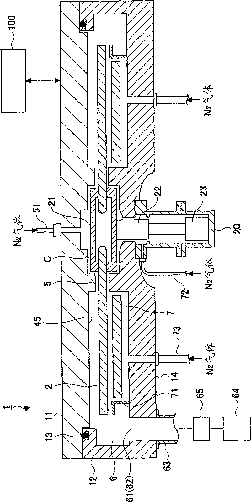
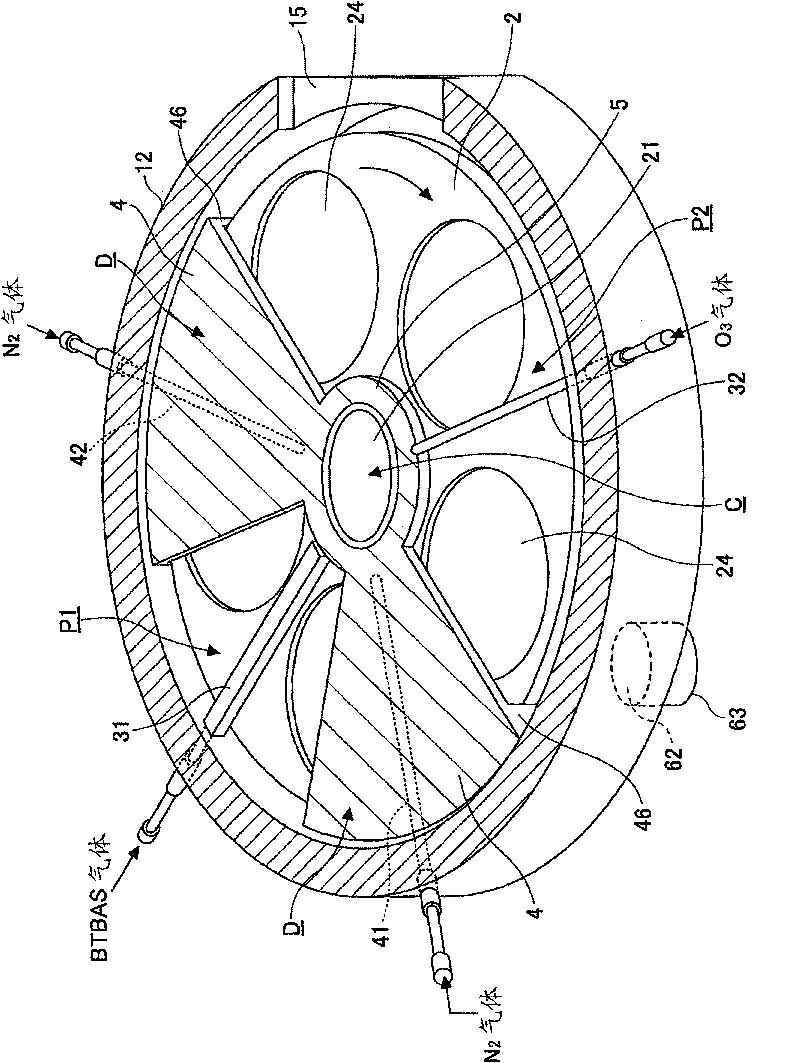
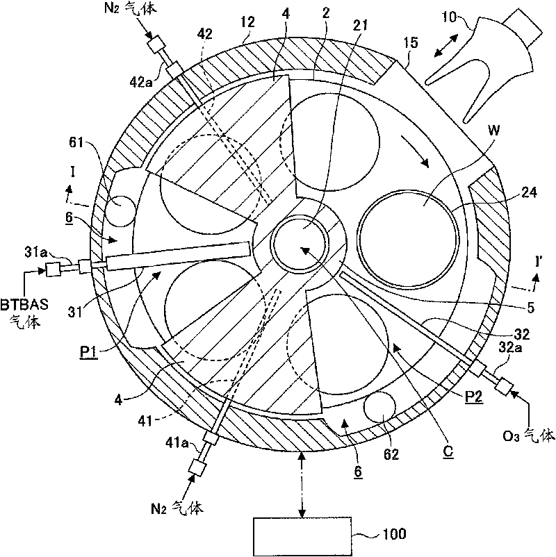
Gas injector and film deposition apparatus

An injection device and gas injection technology, which is applied in the direction of injection devices, injection devices, electrical components, etc., can solve the problems of long processing time, reaction product adhesion, and long time consumption

Active Publication Date: 2010-06-16
TOKYO ELECTRON LTD
View PDF8 Cites 12 Cited by
  • Summary
  • Abstract
  • Description
  • Claims
  • Application Information

AI Technical Summary

Problems solved by technology

However, the above-mentioned film-forming method has the following problems: it takes a long time to replace the gas with the purge gas, and the number of repeated cycles is large, for example, hundreds of times, so the processing time is long, and it is desired to be able to process at a high speed. Apparatus and method for processing productivity
[0004] Based on such a background, Patent Document 1 to Patent Document 8 describe devices for arranging a plurality of substrates on a rotary table in a vacuum container along the rotation direction to perform film formation processing, but the film formation devices described in these documents There are problems such as particles and reaction products sticking to the wafer, and it takes a long time to purge or reacts in unnecessary areas.

Method used


Image

  • Gas injector and film deposition apparatus
  • Gas injector and film deposition apparatus
  • Gas injector and film deposition apparatus

Examples


Embodiment 1

[0121] As the first reactant gas supply unit, a Figure 8 ~ Figure 1 The concentration distribution of the BTBAS gas directly under the gas injection device 31 was simulated using the gas injection device 31 having the same structure as the gas injection device shown in the embodiment of 0. Figure 20A A longitudinal sectional side view of the gas injection device 31 used in the simulation is schematically shown. In addition, the design conditions of the gas injection device 31 are as follows.

[0122] Diameter of gas outflow hole 313: 0.5mm

[0123]Spacing between centers of gas outflow holes 313: 5.0mm

[0124] The number of arranged gas outflow holes 313: 67

[0125] Slit width of gas ejection port 316: 0.3 mm

[0126] Height H1 from the upper surface of the turntable 2 (wafer W surface) to the gas ejection port 316: 4mm

Embodiment 2

[0128] As the first reactant gas supply unit, a Figure 12 , Figure 13 The gas injection device 31a having the same structure as the gas injection device shown in another embodiment of the present invention simulated the concentration distribution of the BTBAS gas directly below the gas injection device 31a. Figure 20B A longitudinal sectional side view schematically shows a gas injection device 31a used in the simulation. In addition, the design conditions of the gas injection device 31a are as follows.

[0129] Diameter of gas outflow hole 313: 0.5mm

[0130] Interval between centers of gas outflow holes 313: 10 mm

[0131] The number of arranged gas outflow holes 313: 32

[0132] The slit width of the gas ejection port 316: 2.0mm

[0133] Height H1 from the upper surface of the turntable 2 (wafer W surface) to the gas ejection port 316: 4mm


PUM


Abstract

An injector body of a gas injector has a gas inlet and a gas passage; plural gas outflow openings disposed on a wall part of the injector body along a longitudinal direction of the injector body; and a guide member that provides a slit-shaped gas discharge opening extending in the longitudinal direction of the injector body on an outer surface of the injector body, and guides gas flowing from thegas outflow openings to the gas discharge opening.

Description

technical field [0001] The invention relates to a gas injection device and a film forming device. Background technique [0002] As a film-forming method in a semiconductor manufacturing process, there is known a process in which a first reactant gas is adsorbed on the surface of a semiconductor wafer (hereinafter simply referred to as "wafer") as a substrate in a vacuum atmosphere, and then supplied The gas is switched to the second reaction gas, and one or more layers of atomic layers and molecular layers are formed by the reaction of the two gases, and this cycle is repeated many times to stack these layers and form a film on the substrate. This process is called, for example, ALD (Atomic Layer Deposition), MLD (Molecular Layer Deposition), etc. (hereinafter referred to as ALD method), and can control the film thickness with high precision according to the number of repeated cycles, and the in-plane uniformity of film quality It is also good, and it is an effective method...

Claims


Application Information

Patent Timeline
Patent Type & Authority Applications(China)
IPC IPC(8): C23C16/455H01L21/00
CPCB05B1/20C23C16/45523C23C16/45551C23C16/45578B05B13/0242B05B1/267C23C16/4584
Inventor 加藤寿竹内靖本间学菊地宏之
Owner TOKYO ELECTRON LTD
Learn More