


Quick Research
Generate reliable direction feasibility study reports for your R&D in just a few steps.

Technical Q&A
Discover and master advanced knowledge NOW. Basics, ideas, possibilities, all at once.

Find Solutions
As an expert in R&D theories, this can generate solutions to your technical problems instantly.

Evaluate Feasibility
Analyze your overall solution with one click, know your potential R&D risks in advance.

Monitor Landscape
Get weekly tech updates, stay abreast of the latest tech innovations and key insights.
Power tool
A technology for electric tools and motors, applied in power tools, manufacturing tools, electric components, etc., can solve problems such as temperature rise of switching elements, and achieve the effects of preventing vibration, improving cooling effect, and improving efficiency
- Summary
- Abstract
- Description
- Claims
- Application Information
AI Technical Summary
Problems solved by technology
Method used
Image


Examples
Embodiment Construction
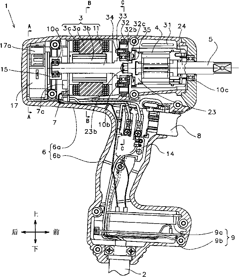
[0033] Embodiments according to the present invention will be described below with reference to the drawings. In the following description of the specification of the present invention, an oil pulse tool is used as an example of an electric tool; and the above, below, front, and rear mentioned in the following description are figure 1 Shown above, below, front, rear.
[0034] figure 1 is an overall sectional view of an oil pulse tool according to an embodiment of the present invention. This oil pulse tool 1 uses power supplied from the outside through a power cord 2, uses a motor 3 as a drive source, and uses the motor 3 to drive an oil pulse unit 4 serving as a power transmission mechanism so as to apply rotational force and impact force to On the output shaft 5 connected with the oil pressure pulse unit 4, thereby the rotational impact force is continuously or intermittently transmitted to a front end tool (not shown) such as a quill bit, so as to perform such as screw fas...
PUM
 Abstract
Description
Claims
Application Information
 - R&D Engineer
- R&D Manager
- IP Professional
- Industry Leading Data Capabilities
- Powerful AI technology
- Patent DNA Extraction
Browse by: Latest US Patents, China's latest patents, Technical Efficacy Thesaurus, Application Domain, Technology Topic, Popular Technical Reports.
© 2024 PatSnap. All rights reserved.Legal|Privacy policy|Modern Slavery Act Transparency Statement|Sitemap|About US| Contact US: help@patsnap.com