


Quick Research
Generate reliable direction feasibility study reports for your R&D in just a few steps.

Technical Q&A
Discover and master advanced knowledge NOW. Basics, ideas, possibilities, all at once.

Find Solutions
As an expert in R&D theories, this can generate solutions to your technical problems instantly.

Evaluate Feasibility
Analyze your overall solution with one click, know your potential R&D risks in advance.

Monitor Landscape
Get weekly tech updates, stay abreast of the latest tech innovations and key insights.
Air exchange fan
A technology for ventilating fans and wall components, which is applied to the components of pumping devices for elastic fluids, non-variable pumps, machines/engines, etc., can solve the problems of increasing the complexity and inconvenience of maintenance, and achieve easy maintenance, The effect of easy installation
- Summary
- Abstract
- Description
- Claims
- Application Information
AI Technical Summary
Problems solved by technology
Method used
Image


Examples
Embodiment Construction
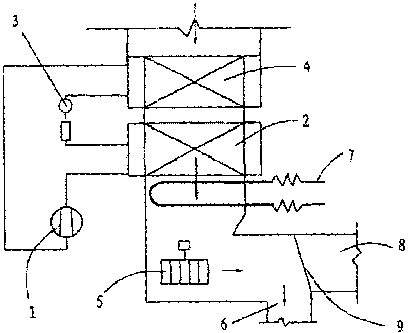
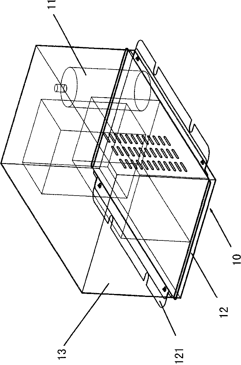
[0022] For ease of expression, the above and below mentioned in the entire specification of the present invention are based on the orientation of the ventilation fan after installation.
[0023] Figure 2A , 2B It is a schematic diagram of the first embodiment of the present invention. like Figure 2A As shown, the ventilation fan 100 is composed of a frame 200 and a body (not shown) in the frame. The frame 200 is composed of a bottom part 210 , a wall part 220 and a top part 230 . Wherein the bottom part 210 is made up of several bottom components 211, which are collectively referred to as the heat exchanger (not shown in the figure), fan (not shown in the figure), compressor (not shown in the figure) and other components of the body, which are independently installed in several on the bottom assembly 211.
[0024] Each bottom assembly 211 is independently installed on the wall part 220 , and the connection between the bottom assembly 211 and the wall part 220 is respect...
PUM
 Abstract
Description
Claims
Application Information
 - R&D Engineer
- R&D Manager
- IP Professional
- Industry Leading Data Capabilities
- Powerful AI technology
- Patent DNA Extraction
Browse by: Latest US Patents, China's latest patents, Technical Efficacy Thesaurus, Application Domain, Technology Topic, Popular Technical Reports.
© 2024 PatSnap. All rights reserved.Legal|Privacy policy|Modern Slavery Act Transparency Statement|Sitemap|About US| Contact US: help@patsnap.com