Stall detection by use of pressure sensors

A pressure and stall technology, applied in the field of blade stall and wind turbine installations, can solve the problems of fluid stall, increased lift at the angle of attack, suspension of lift, etc., and achieves the effect of avoiding blade performance degradation and high lift-drag ratio.

Inactive Publication Date: 2010-06-09
SIEMENS AG
View PDF0 Cites 8 Cited by
  • Summary
  • Abstract
  • Description
  • Claims
  • Application Information

AI Technical Summary

Problems solved by technology

An increase in the angle of attack corresponding to the blade pitch, relative to the flow direction of the fluid flow, increases lift and also causes a fluid stall along the suction side of the blade
Therefore, if a stall occurs in the fluid flow along the suction side, the fluid flow no longer attaches but detaches, and lift ceases

Method used


Image

  • Stall detection by use of pressure sensors
  • Stall detection by use of pressure sensors
  • Stall detection by use of pressure sensors

Examples


Embodiment Construction

[0035] The figures shown are schematic only. It should be noted that in different drawings, the same or similar elements are marked with the same reference numerals, or the reference numerals differ from the corresponding reference numerals only in the first position.

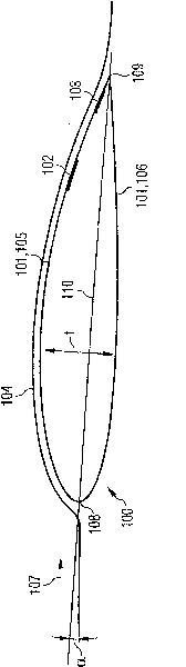
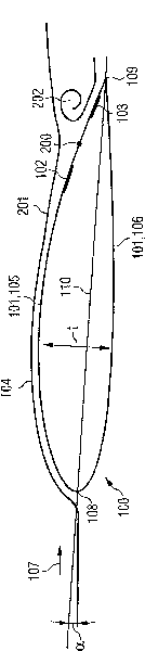
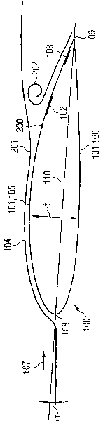
[0036] figure 1 A blade 100 of a wind turbine 400 is shown. The blade 100 comprises a blade surface 101 and a pressure measurement device 102 providing a pressure value for stall detection. The pressure measurement device 102 is located at the blade surface 101 such that the pressure of the fluid 104 flowing along the blade surface 101 can be measured by the pressure measurement device 102 .

[0037] By measuring the pressure of the fluid 104 flowing along the blade surface 101 , a stall region of the fluid flowing along the surface or a separated flow region of the fluid 104 can be detected. Thus, a stall of the fluid 104 from the blade surface 101 can be detected. Stalling of the fluid 104 may occur due t...


PUM


Abstract

The present invention relates to a blade (100) for a wind turbine (400). The blade (100) comprises a blade surface (101) and a pressure gauge device (102) for providing a pressure value for being used for stall detection. The pressure gauge device (102) is located at the blade surface (101) in such a manner, that a pressure of a fluid (104) that flows along the blade surface (101) is measurable by the pressure gauge device (102).

Description

technical field [0001] The invention relates to the field of wind turbines. Furthermore, the invention relates to a blade for a wind turbine and to a wind turbine arrangement comprising at least one blade. Furthermore, the invention relates to a method of detecting a stall of a blade for a wind turbine. Background technique [0002] In wind turbines, the wind turbine blades are adjusted for an optimal pitch strategy. That is, wind turbine blades are designed and tuned to determine the optimum relationship between lift and drag on the blade. [0003] Wind turbine blades provide a blade profile comprising a leading edge and a trailing edge. The leading edge comprises a leading stagnation point at which a fluid, such as air, flows towards the wind turbine blade. The fluid flow is split from the forward stagnation point with a first part of the flow flowing over one blade surface and another part of the fluid flow flowing over the other blade surface of the wind turbine blad...

Claims


Application Information

Patent Timeline
Patent Type & Authority Applications(China)
IPC IPC(8): F03D1/06F03D7/04
CPCF05B2270/324Y02E10/723Y02E10/722F03D11/0091F05B2270/808Y02E10/72F05B2270/3015F05B2270/301F03D7/0224Y02E10/721F03D17/00
Inventor P·B·埃尼沃尔德森I·弗里登达尔J·劳尔森
Owner SIEMENS AG
Why Eureka
Try Eureka