
Digital ink-jet textile printing machine

A digital inkjet and printing machine technology, applied in printing, typewriters, printing devices, etc., can solve the problems of increased wind effect of ink droplets, non-parallel error, deviation of cloth running process, etc. Printing accuracy, the effect of increasing friction

Inactive Publication Date: 2012-12-26
梁健
View PDF0 Cites 0 Cited by
  • Summary
  • Abstract
  • Description
  • Claims
  • Application Information

AI Technical Summary

Problems solved by technology

[0005] 2. Due to the defects in the manufacturing of the conveyor belt, the processing error of the conveyor belt support roller and the non-parallel error caused by the installation, the fabric will be offset during the running process
[0006] 3. The conveyor belt will be aging after long-term use, and needs to be adjusted, maintained or even replaced frequently
[0007] 4. The wider the conveyor belt is, the more difficult it is to manufacture, the higher the cost, and the more difficult it is to install; therefore, it is very difficult to manufacture a wide-format printing machine with a conveyor belt structure
[0008] 5. The machine with this structure is bulky, difficult to transport, and occupies a large area
[0009] 6. Theoretically, the closer the distance between the nozzle and the object to be sprayed, the better the printing quality, usually below 3mm; and in order to prevent the fabric from slightly wrinkling, bulging and scratching the nozzle, the conveyor belt machine will reduce the distance between the cloth and the nozzle Adjust it to more than 4-6 mm; therefore, when the nozzle is moving to spray ink, the influence of the wind force on the ink droplet will increase, which is not conducive to the accuracy of inkjet printing

Method used

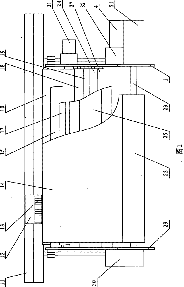
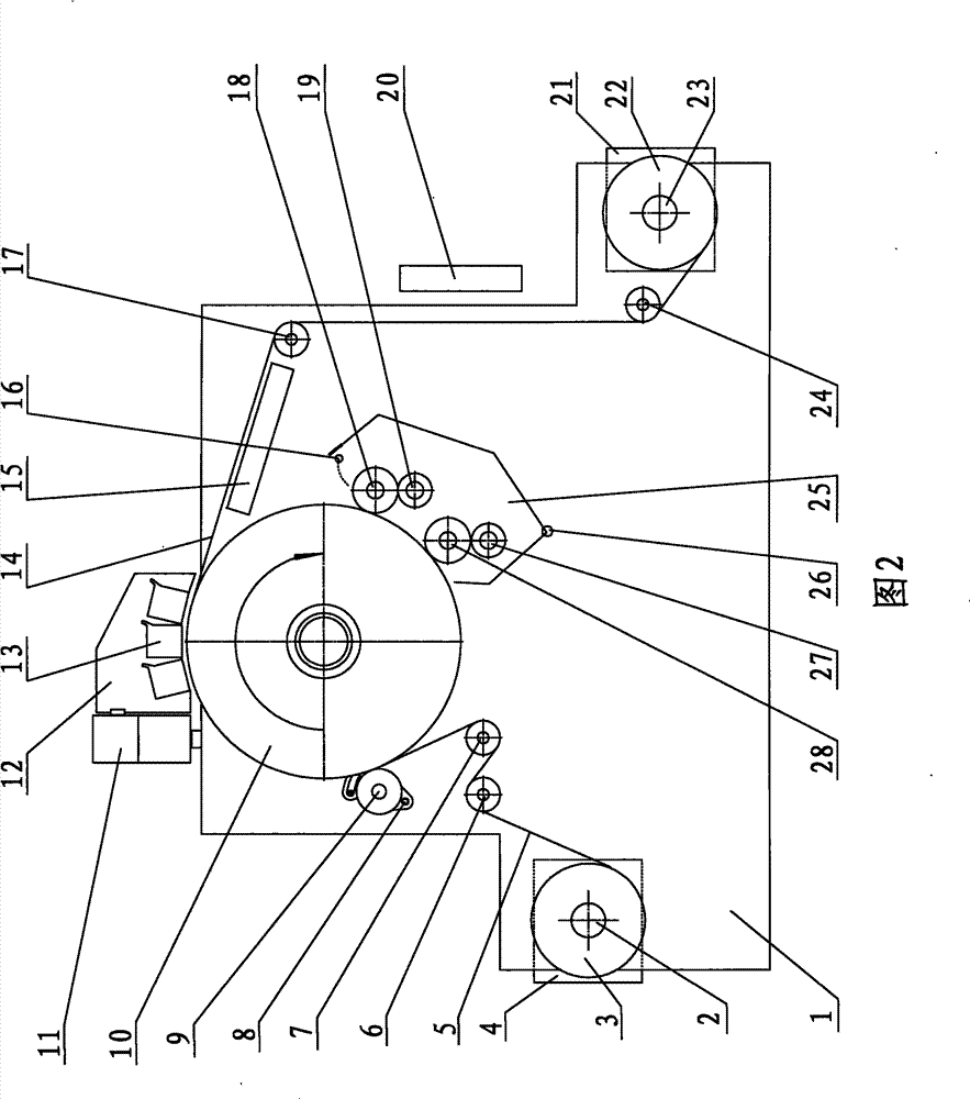
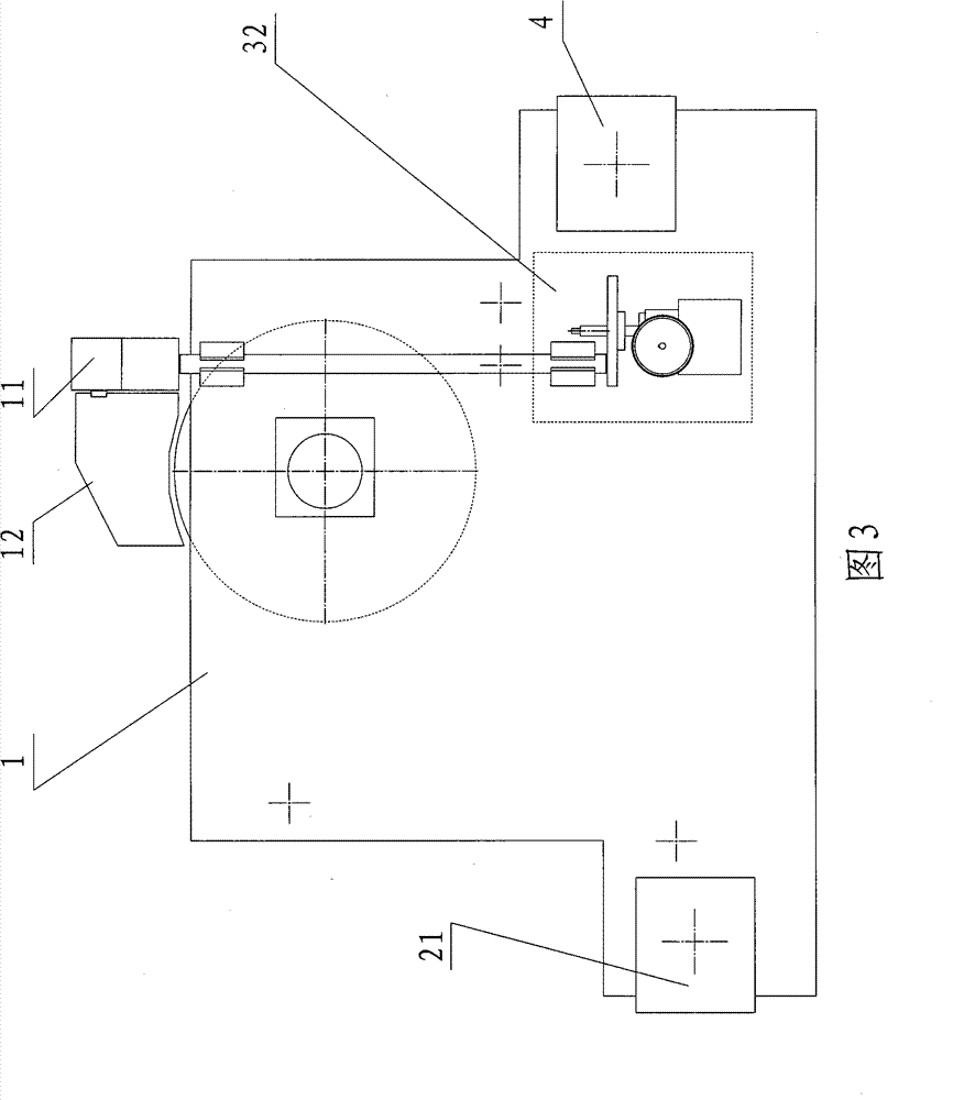

Image

  • Digital ink-jet textile printing machine
  • Digital ink-jet textile printing machine
  • Digital ink-jet textile printing machine

Examples


Embodiment Construction

[0029] The present invention will be described in further detail below in conjunction with the accompanying drawings.

[0030] like Figure 1~4 Shown, the present invention comprises left wallboard 29, right wallboard 1 and is installed in the discharge device between two wallboards, receiving device, first guide roller 6, flattening roller 7, leaning against roller 9, main The driving drum 10, the second guide roller 17, the third guide roller 24 and the cleaning device.

[0031] The left and right wall panels 29, 1 are connected by multiple supporting beams 45 to form a main frame structure. The main driving drum 10 as driving roller is rotatably installed on the left and right wallboards 29,1 by bearings, and is driven by the main driving motor 31 installed on the right wallboard 1. The receiving and discharging devices are respectively located on both sides of the main driving drum 10. The discharging device is composed of a discharging roller 2 and a roll 3 to be printe...


PUM


Abstract

The invention relates to textile printing equipment, in particular to a digital ink-jet textile printing machine capable of personalized jet printing. The digital ink-jet textile printing machine comprises a main driving roller used as a driving roll, a material feeding device, a material receiving device, a guide rail unit and a nozzle set unit, wherein the main driving roller, the material feeding device and the material receiving device are rotatably arranged between two parallel wall plates; the material receiving device and the material feeding device are respectively arranged at both sides of the main driving roller and parallel to the main driving roll; the guide rail unit is arranged on the wall plates at both sides with synchronous lifting; and the nozzle set unit is arranged above the main driving roller and can be arranged on the guide rail unit in a reciprocating way. The digital ink-jet textile printing machine has the advantages of good synchronism, high jet printing precision, wide jet printing material breadth, no pollution of jet printing materials and devices, long service life, wide application range, and the like.

Description

technical field [0001] The invention relates to textile printing equipment, in particular to a digital ink-jet textile printing machine capable of individualized spray printing. Background technique [0002] At present, the personalized demand for textile printing is increasing; therefore, digital inkjet printing equipment is deeply loved by industry personnel because it does not require plate making, can be produced in a single piece, and can be printed in batches. [0003] Most of the existing digital inkjet textile printing machines use a conveyor belt structure. The fabric is pasted on the conveyor belt and steps. Above the conveyor belt, there is a track perpendicular to the forward direction of the fabric. The nozzle group moves reciprocally and scanningly along the track. Printing ink on fabric. The digital inkjet textile printing machine with this structure has the following disadvantages: [0004] 1. Since the fabric is floating on the surface of the conveyor belt...

Claims


Application Information

Patent Timeline
Patent Type & Authority Patents(China)
IPC IPC(8): B41J2/01B41J2/165B41J11/00B41J23/02B41J3/407
CPCB41J29/17B41J3/4078B41J2025/008B41J15/046B41J11/0022
Inventor 梁健
Owner 梁健
Learn More