Electric locking and rotating joint for auxiliary arm for surgical operation

A technique for surgery and rotary joints, which is used in surgery, medical science and other directions to achieve reliable locking and loosening, strong versatility and excellent performance.

Inactive Publication Date: 2011-04-27
昆山市工业技术研究院有限责任公司
View PDF4 Cites 0 Cited by
  • Summary
  • Abstract
  • Description
  • Claims
  • Application Information

AI Technical Summary

Problems solved by technology

[0002] We know that in various fields such as industry, agriculture and medical treatment, there are problems with the braking and relaxation of the rotary joints of the manipulator, especially for medical surgery For surgical robotic arms, performance indicators such as the reliability of the braking and release of the rotary joint, locking force, and safety put forward higher requirements for the structure of the rotary joint, because the mechanical arm used to assist minimally invasive surgery It is fixed on the operating bed, so the joint structure is required to be compact, small in size, and light in weight. At present, the locking and loosening of the rotating joints of many robotic arms are realized by electromagnetic brakes, which are not only large in size and heavy in weight. Moreover, the braking noise is relatively large, and the locking force cannot be adjusted according to needs. Therefore, it is very important to design a rotary joint with adjustable locking force, compact structure, and good reliability.

Method used


Image

  • Electric locking and rotating joint for auxiliary arm for surgical operation
  • Electric locking and rotating joint for auxiliary arm for surgical operation
  • Electric locking and rotating joint for auxiliary arm for surgical operation

Examples


specific Embodiment approach

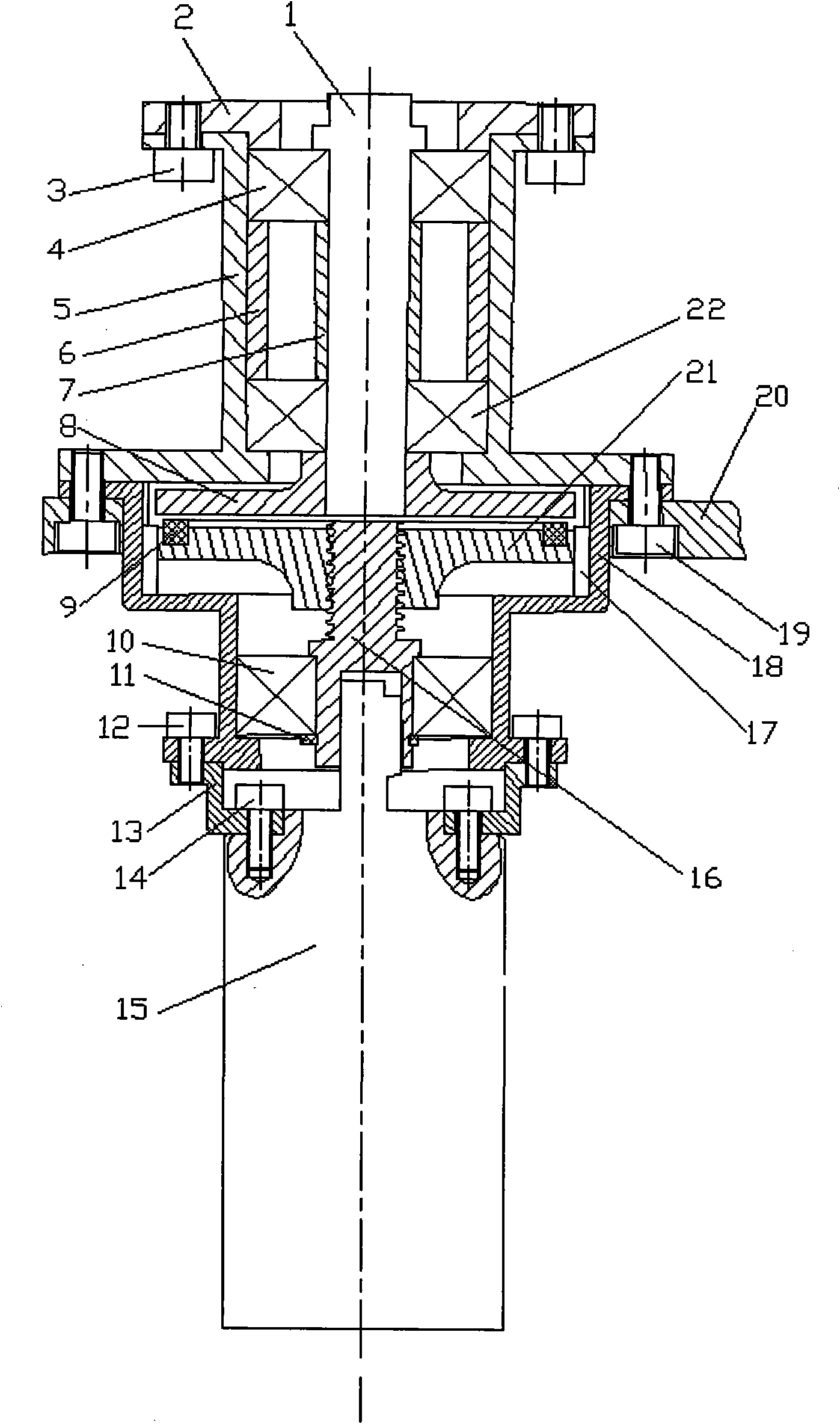
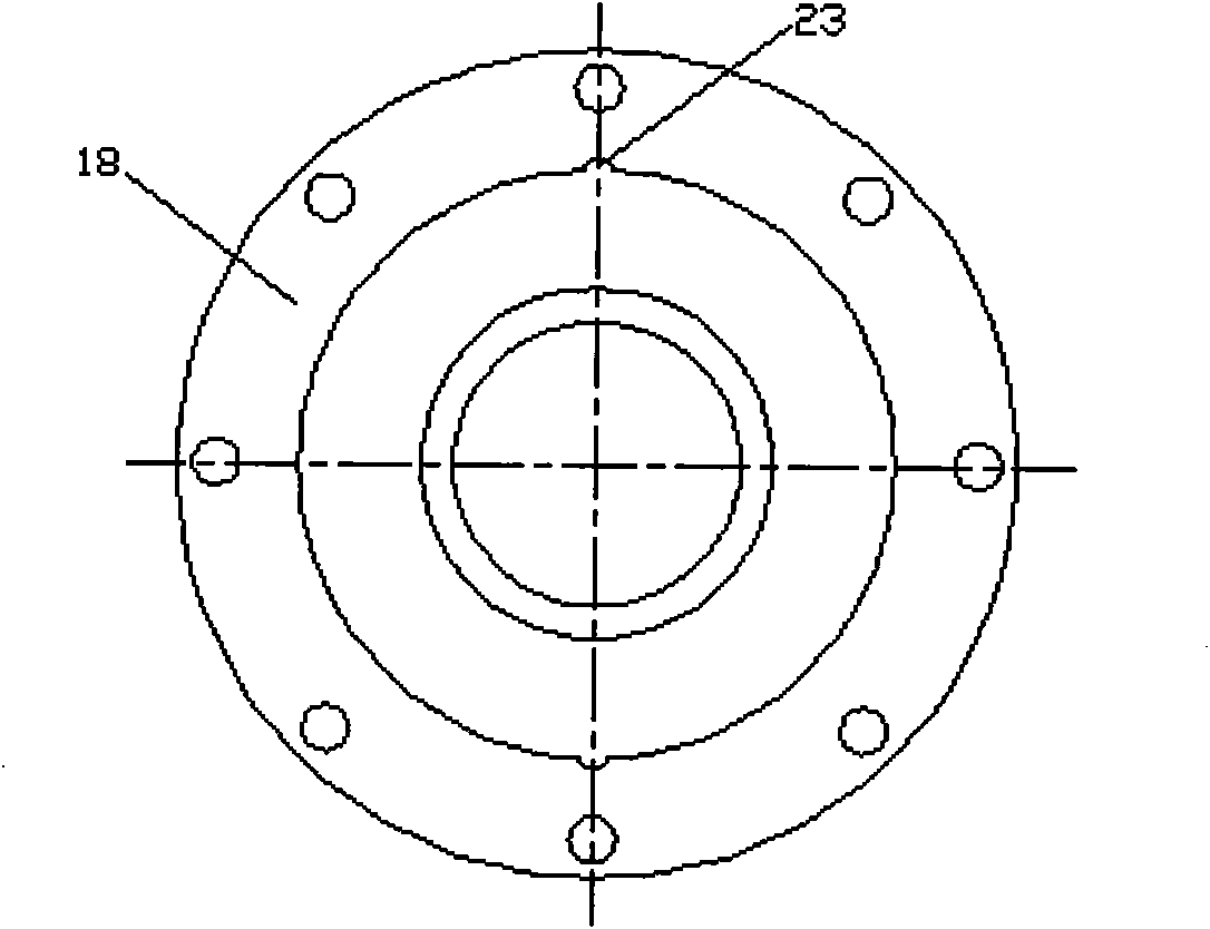
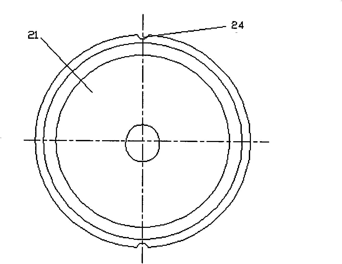
[0034] figure 1 It is a structural schematic diagram of an embodiment of the present invention; figure 2 It is a structural schematic diagram of the locking outer sleeve according to the present invention; image 3 It is a structural schematic diagram of the trapezoidal nut described in the present invention.

[0035] Such as Figure 1 to Figure 3 Shown: Electric locking rotary joint for surgical auxiliary arm, including joint rotation mechanism and joint locking mechanism, the joint rotation mechanism is located on the upper part of the joint locking mechanism, wherein:

[0036] The joint rotation mechanism includes a joint rotating shaft 1, a joint bearing cover 2, a joint bearing seat 5 and a joint chassis 8. The joint rotating shaft 1 is an output shaft of the present invention, which is connected with a load, and the joint bearing cover 2 is located on the upper part of the joint rotating shaft 1, and its It is fixedly connected with the joint bearing seat 5 located ...


PUM


Abstract

The invention discloses an electric locking and rotating joint for an auxiliary arm for surgical operation, which is characterized in that the electric locking and rotating joint comprises a joint rotating mechanism and a joint locking mechanism, the joint rotating mechanism is positioned at the upper part of the joint locking mechanism, wherein the joint rotating mechanism comprises a joint rotary shaft, a joint bearing cap, a joint bearing seat and a joint chassis, the joint locking mechanism comprises a locking outer sleeve, a friction ring, a trapezoidal nut, a lead screw shaft and a motor, an output shaft of the motor drives the lead screw shaft to move, the lead screw shaft drives the trapezoidal nut which is in threaded connection with the lead screw shaft to move, and the trapezoidal nut is circumferentially fixed by the locking outer sleeve arranged on the outside of the trapezoidal nut and can only move up and down, thereby driving the friction ring arranged at the upper part to move up and down; and friction force is produced when the friction ring is in contact with the joint chassis, the friction force is eliminated when the friction ring and the joint chassis are separated, and the joint rotary shaft is in threaded connection with the joint chassis, thereby realizing locking or unlocking of the joint rotary shaft. The electric locking and rotating joint has the advantages of compact structure, convenient operation and maintenance, reliable locking and unlocking and excellent performances.

Description

technical field [0001] The invention relates to an electric locking rotary joint, in particular to an electric locking rotary joint used for a surgical operation auxiliary arm, and belongs to the technical field of medical surgical operation auxiliary equipment. Background technique [0002] We know that in various fields such as industry, agriculture, and medical treatment, there are problems with the braking and relaxation of the rotary joints of the mechanical arm, and especially for the mechanical arms used in medical surgery, the braking and relaxation of the rotary joints Performance indicators such as reliability, locking force, and safety put forward higher requirements for the structure of the rotary joint. Since the mechanical arm used to assist minimally invasive surgery is fixed on the operating bed, the joint is required to be compact and small in size. , light weight, and the locking and loosening of many mechanical arm rotary joints are realized by electromag...

Claims


Application Information

Patent Timeline
Patent Type & Authority Patents(China)
IPC IPC(8): A61B17/00
Inventor 李超唐粲王峰程胜张建伟
Owner 昆山市工业技术研究院有限责任公司
Why Eureka
Try Eureka