
Online detection and calibration method for Hall current sensor

A technology of Hall current and calibration method, which is applied in the direction of instruments, measuring devices, measuring electrical variables, etc., to achieve the effect of solving bias errors, improving measurement accuracy, and avoiding unnecessary losses

Active Publication Date: 2010-06-02
CHINA ELECTRIC POWER RES INST +2
View PDF1 Cites 45 Cited by
  • Summary
  • Abstract
  • Description
  • Claims
  • Application Information

AI Technical Summary

Problems solved by technology

And the patent application 200420114935.4 can only detect whether the Hall current sensor is working normally and give an alarm

Method used


Image

  • Online detection and calibration method for Hall current sensor
  • Online detection and calibration method for Hall current sensor
  • Online detection and calibration method for Hall current sensor

Examples


Embodiment Construction

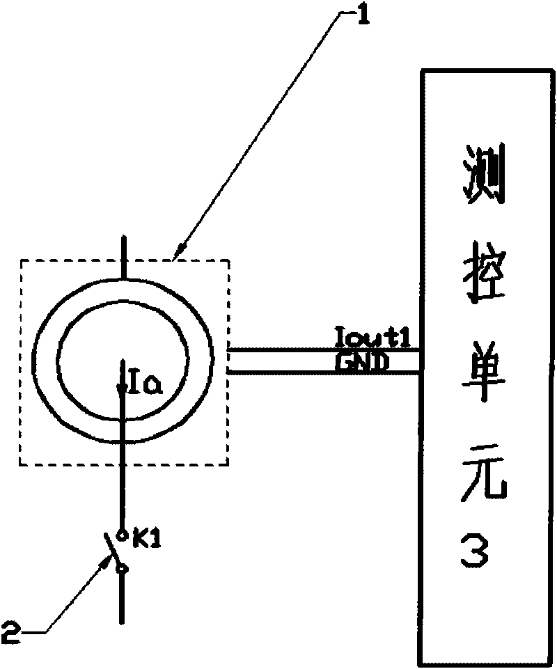
[0016] figure 1 Shown is the block diagram of the traditional Hall current sensor measurement method, in the figure (1) is the Hall current sensor for measurement, Ia is the measured current, (2) is the switch of the measurement current loop, (3) is the measurement and control unit, with It is used to receive the output current signal of the measuring sensor.

[0017] The input measurement circuit of the Hall current sensor (1) for measurement is Ia, and the output circuit is connected with the measurement and control unit (3). Its main feature is to complete a single measurement function. When the measured circuit has a current Ia passing through it, the sensor output signal circuit will get the Iout1 current signal output according to a fixed ratio. This signal will be processed by the measurement and control unit to obtain the measured value. If the Hall current sensor is biased or damaged, the sensor output signal circuit will not get the current signal output according t...


PUM


Abstract

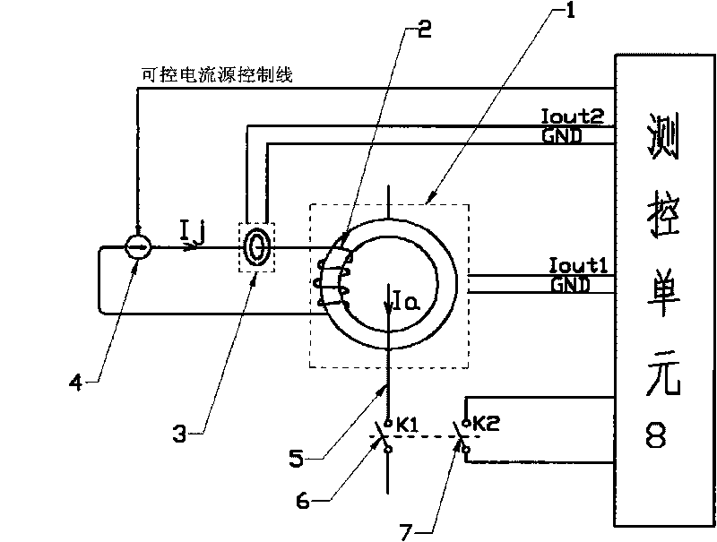
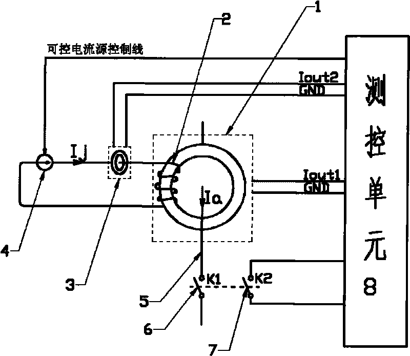
The invention provides an online detection and calibration method for a Hall current sensor. In power system application, the Hall current sensor is often impacted by grid fault current or thunder strike to cause bias magnet and damage of the Hall current sensor. In the method, a calibration coil, and auxiliary elements which assist calibrating the Hall current sensor and calibrate a current generator and the like are arranged in the Hall current sensor so as to realize the online detection and calibration of the Hall current sensor. The online detection and calibration method for the Hall current sensor has the advantages that: on the one hand, the measurement accuracy of the Hall current sensor can be improved and a bias magnet error problem can be solved; and on the other hand, a fault sensor can be discovered timely.

Description

technical field [0001] The invention relates to the fields of electrical quantity measurement and microprocessor control, in particular to an online automatic calibration method for a Hall current sensor. Background technique [0002] In the application of using the Hall current sensor to measure the DC current at the neutral point of the transformer, because the inrush current of tens of thousands of amperes often occurs at the neutral point of the transformer, the current value is thousands of times the measurement range of the Hall current sensor, resulting in the magnetic field of the Hall current sensor. biased or damaged. In practical applications, when the Hall current sensor is magnetically biased, the measurement error increases; when the Hall current sensor is damaged, it is difficult to be found in time, resulting in measurement errors. [0003] Chinese patent application 200420114935.4 provides a fault detection circuit for a Hall current sensor, including a Hal...

Claims


Application Information

Patent Timeline
Patent Type & Authority Applications(China)
IPC IPC(8): G01R35/02
Inventor 张辉张金平张丽坤王伟涛
Owner CHINA ELECTRIC POWER RES INST
Learn More