
Device for testing dynamic stiffness and constant pressure of high-speed electric spindle

A high-speed motorized spindle, dynamic stiffness technology, used in measuring devices, using stable tension/pressure to test the strength of materials, testing of mechanical parts, etc. The performance is difficult to predict, and the loading cannot be constant, etc., to achieve the effect of convenient data acquisition, real-time measurement, and stable dynamic loading.

Inactive Publication Date: 2011-11-09
CHONGQING UNIV
View PDF0 Cites 0 Cited by
  • Summary
  • Abstract
  • Description
  • Claims
  • Application Information

AI Technical Summary

Problems solved by technology

However, when the spindle obtains extremely high rotation speed, it also creates complex mechanical, electrical, magnetic and thermal coupling relationships inside the system, making it difficult to predict the static and dynamic performance of the spindle during rotation. As an emerging In the field of high-speed electric spindles, many problems urgently need to be solved in the application, such as dynamic balance, spindle temperature rise, torque output capability, static stiffness, dynamic stiffness, thermal deformation and spindle runout, etc. The dynamic performance of the electric spindle, although the device is simple and the cost is low, is difficult to control and test, and the large amount of frictional heat and mechanical wear generated by the high-speed operation of the spindle cannot achieve non-destructive loading, and the loading cannot be constant, which reduces the test accuracy. more difficult to control
With the development of science and technology, the rotation speed of the spindle is getting higher and higher, making many traditional spindle performance testing techniques no longer suitable for the performance testing requirements of high-speed electric spindles

Method used


Image

  • Device for testing dynamic stiffness and constant pressure of high-speed electric spindle
  • Device for testing dynamic stiffness and constant pressure of high-speed electric spindle
  • Device for testing dynamic stiffness and constant pressure of high-speed electric spindle

Examples


Embodiment Construction

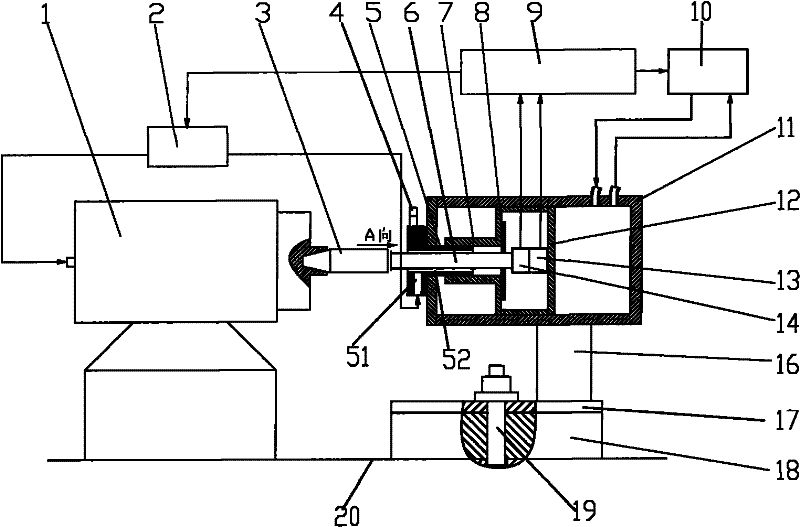
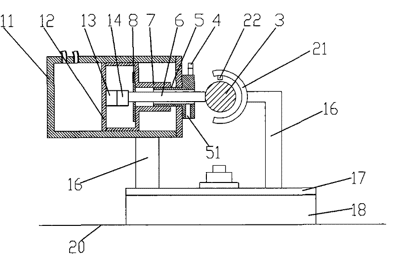
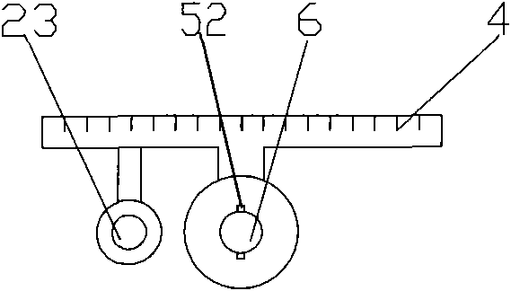
[0021] figure 1 It is a schematic diagram of the axial detection structure of the electric spindle of the present invention, image 3 for figure 1 View along direction A, Figure 4 It is a schematic diagram of the connection mode between the bracket 1 and the mounting plate, as shown in the figure: the high-speed electric spindle dynamic stiffness constant pressure testing device of the present embodiment includes a base 18, a loading system, a lubrication cooling system and an automatic control unit 9;

[0022] The loading system includes a hydraulic cylinder assembly, a hydraulic cylinder oil circuit system 10, and a loading rod 6. The hydraulic cylinder assembly includes a cylinder body 11 and a piston 12. One end of the loading rod 6 penetrates the piston axially in an axially slidable manner. 12, and a pressure sensor 14 is set between the end face and the piston 12, as shown in the figure: the piston has an open end structure, the loading rod penetrates into the piston...


PUM


Abstract

The invention discloses a device for testing dynamic stiffness and constant pressure of a high-speed electric spindle, comprising a base, a loading system, a lubricating and cooling system and an automatic control unit, wherein the loading system comprises a hydraulic cylinder component, a hydraulic cylinder oil way system and a loading rod. In the invention, a loading value and a deformation value are collected through a pressure sensor and a displacement sensor by adopting a hydraulic cylinder and combining the automatic control unit; and the control unit controls the loading pressure of the hydraulic cylinder according to the variation of the loading value and the deformation value and can detect the high-speed electric spindle under the condition of dead load so as to avoid frictionalheating generated by mechanical contact in a high-speed running state of the high-speed electric spindle and influence of mechanical wear to test precision and realize continuous and stable dynamic loading and real-time measurement of the high-speed electric spindle, therefore, the invention has high measurement precision and can conveniently finish various functions including data collection, display, storage, analysis, calculation, control, trigger and the like. The whole device has the advantages of compact structure, convenient use and low cost.

Description

technical field [0001] The invention relates to a detection mechanism, in particular to a high-speed electric spindle dynamic stiffness constant pressure testing device. Background technique [0002] High-speed electric spindle is the product of the rapid development of contemporary high-speed machining technology and theory. It not only satisfies high-speed machining, but also promotes the further development of high-speed machining technology theory. It is an emerging science and technology. Structurally, the driving motor is built in as a part of the rotating mass of the main shaft, and power transmission devices such as belts and gears are omitted, thereby effectively reducing the vibration and noise of the main shaft and making the speed of the main shaft the same as that of the driving motor. The rated speed is synchronized, and its control becomes precise and easy. However, when the spindle obtains extremely high rotation speed, it also creates complex mechanical, el...

Claims


Application Information

Patent Timeline
Patent Type & Authority Patents(China)
IPC IPC(8): G01N3/10G01M13/00
Inventor 陈小安康辉民林利红周明红邢利娜陈文曲
Owner CHONGQING UNIV
Learn More