
Serial siphon valves for fluidic or microfluidic devices

一种连续虹吸阀管、虹吸阀管的技术,应用在阀装置、测量装置、快动装置等方向

Inactive Publication Date: 2010-05-26
UNIV LAVAL
View PDF6 Cites 6 Cited by
  • Summary
  • Abstract
  • Description
  • Claims
  • Application Information

AI Technical Summary

Problems solved by technology

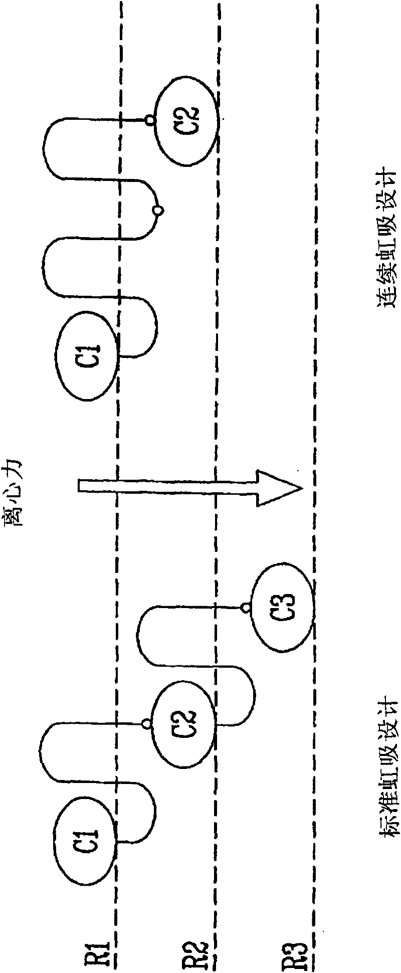
Therefore, capillary valves cannot be used to robustly retard liquid entering downstream chambers in this system

Method used


Image

  • Serial siphon valves for fluidic or microfluidic devices
  • Serial siphon valves for fluidic or microfluidic devices
  • Serial siphon valves for fluidic or microfluidic devices

Examples


example 1

[0076] Example 1: Continuous arrangement of siphon valves in a centripetal fluid platform for controlled fluid release.

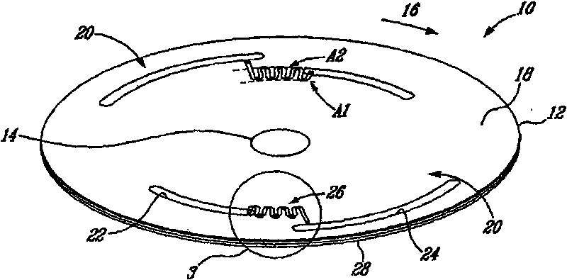
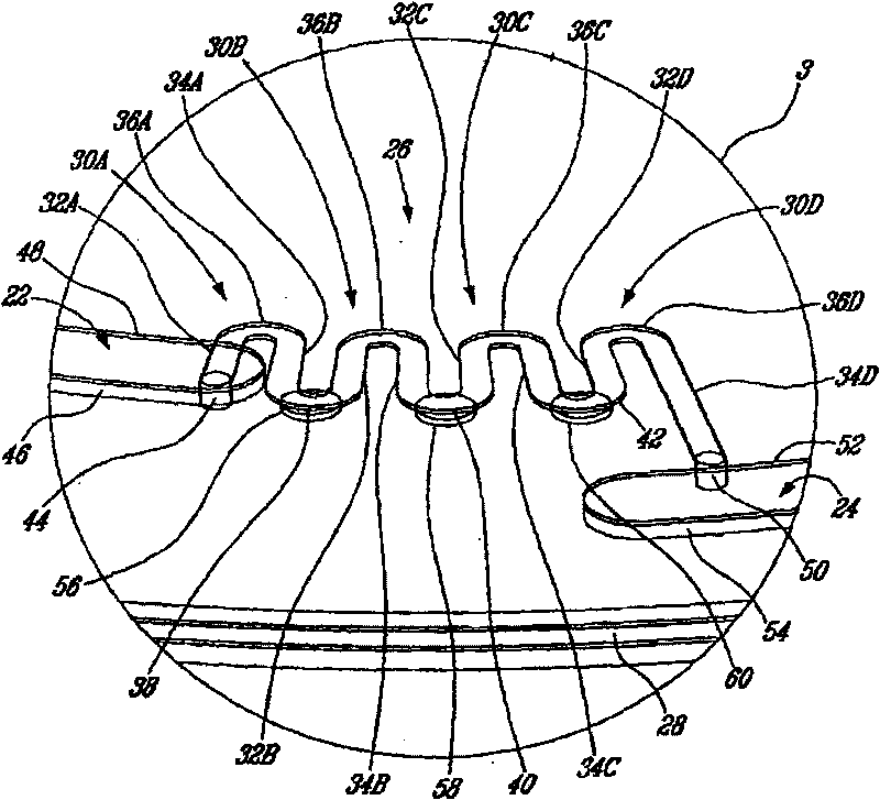
[0077] Figure 7A to Figure 7J The invention is shown in operation. Non-limiting examples of corresponding rotational profiles are also in Figure 8 shown in . More specifically, Figure 8 A rotational profile for controlling the release of liquid L from the upstream chamber 22 into the downstream chamber 24 by using a continuous siphon microfluidic structure such as a continuous siphon valve tube 26 is shown.

[0078] Rotation at 1500 RPM creates a centripetal acceleration that causes the liquid front to travel through the capillary valve. At about 24 seconds (see Figure 7J with Figure 8 ), most of the liquid L from the upstream chamber 22 can be delivered to the downstream chamber 24. In this example, a total of five spinning and stopping cycles are demonstrated. The number of cycles that can be incorporated into this system is limited by the ab...


PUM


Abstract

Methods and devices using a co-radial arrangement of serial siphon structures composed of siphon valves each separated by a capillary valve to save radial space in a fluidrc system. Such serial siphon valves allow to sequentially distribute liquids in a fluidic system upon application of successive centripetal accelerations and decelerations applied to a rotary platform.

Description

[0001] Cross References to Related Applications [0002] This application claims priority to US Provisional Application No. 60 / 904372 filed in the US Patent Office on March 2, 2007, which is hereby incorporated by reference in its entirety. technical field [0003] The invention relates to a fluid device. More particularly but not exclusively, the present invention relates to continuous siphon valves for fluidic devices. Background technique [0004] In the field of centrifugal-based fluidic systems for applications such as immunoassays, nucleic acid analysis, biochemical testing, chemical testing and sample preparation, controlling the release of fluid from the fluid chamber via the rotating rotor is a very important function. This is because the different reagents must often be mixed together at the appropriate times, either in parallel or in succession. [0005] Solutions to this problem include burst valves, standard siphons or mechanical valves depending on the rotati...

Claims


Application Information

Patent Timeline
Patent Type & Authority Applications(China)
IPC IPC(8): G01N33/00B81B5/00B81B7/04C07K1/14
CPCB01L2400/0409F16K99/0001B01L3/502738F16K99/0021F16K99/0063F16K2099/0074G01N21/07B01L2300/0861B01L2300/0803B01L2400/0688F16K2099/0084B01L2200/0621Y10T137/2911Y10T137/87917Y10T137/0753Y10T137/218Y10T137/0989Y10T137/86928
Inventor 米歇尔·G·贝杰龙里吉斯·贝塔维奥拉西奥·吉多马克·马斗
Owner UNIV LAVAL
Learn More