Helicopter rotor wings with commutation net cover

A technology of helicopter rotor and rectifying net, which is applied in the aviation field, can solve the problems of increased body vibration and noise, large force on the hub, and difficult blades, etc., to achieve the goal of improving ride comfort, huge economic benefits, and enhancing national defense strength Effect

Inactive Publication Date: 2013-10-09
吴新保
View PDF0 Cites 0 Cited by
  • Summary
  • Abstract
  • Description
  • Claims
  • Application Information

AI Technical Summary

Problems solved by technology

The disadvantages of this are: the up and down swing of the blade and the back and forth vibration increase the vibration and noise of the machine body, and reduce the efficiency. The rounded leading edge of the blade increases the shock wave resistance generated by the air, and the outer end of the blade When the linear velocity is close to the speed of sound, the linear velocity at the center of the circle is almost zero, so it is difficult for the blade to break through the sound barrier, so that the rotor cannot break through the sound barrier and rotate at supersonic speed, which limits the flight speed of the rotorcraft; and the outer end of the blade is not supported, the hub The force is too large, and the requirements for the material of the blade are high. In the place where there are big trees in the cliff, canyon, ultra-low altitude, high-rise rescue and other operations, the blade is easy to touch the obstacle, which limits the scope of use of the rotor helicopter.

Method used


Image

  • Helicopter rotor wings with commutation net cover
  • Helicopter rotor wings with commutation net cover
  • Helicopter rotor wings with commutation net cover

Examples


Embodiment 1

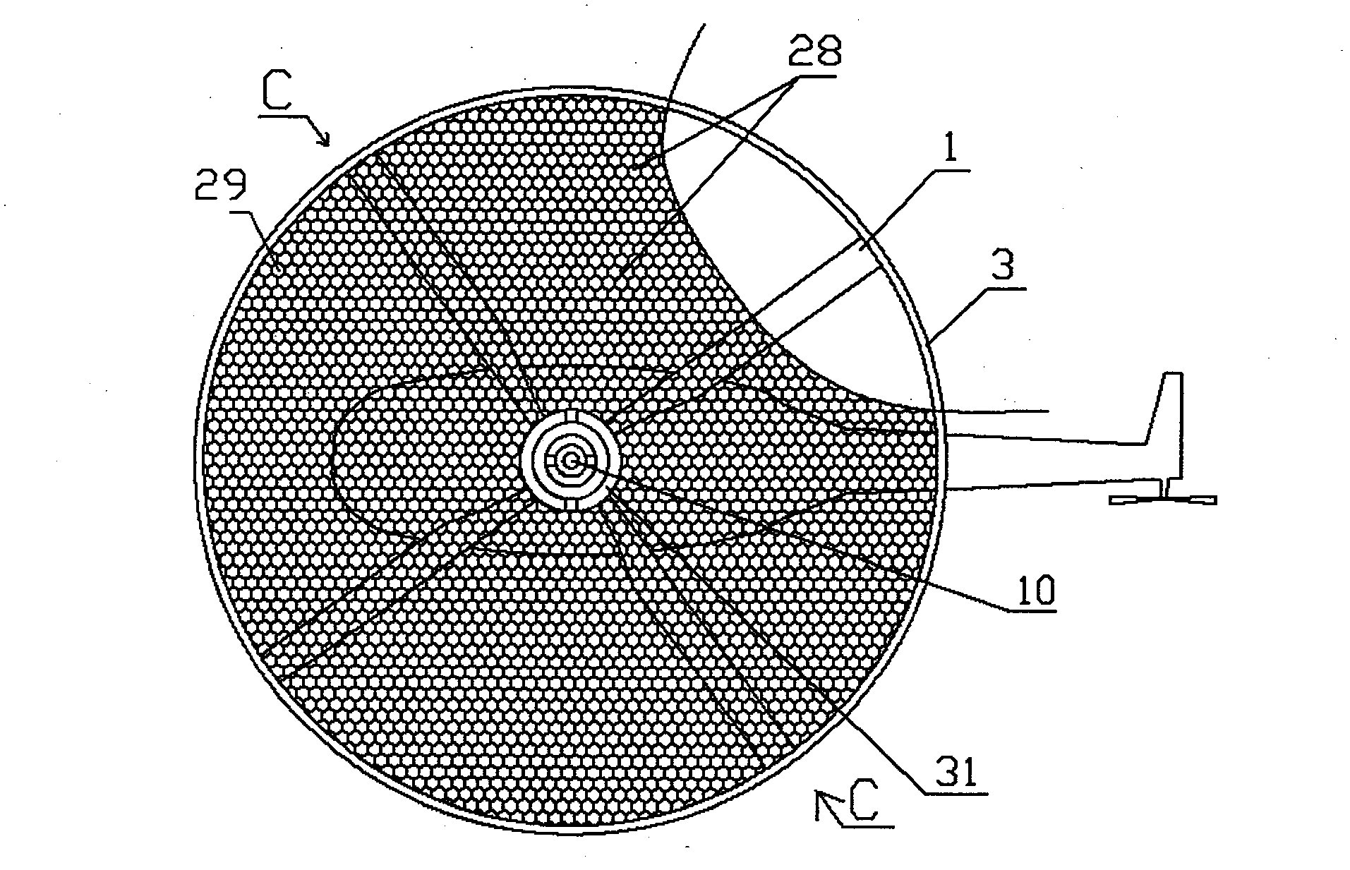
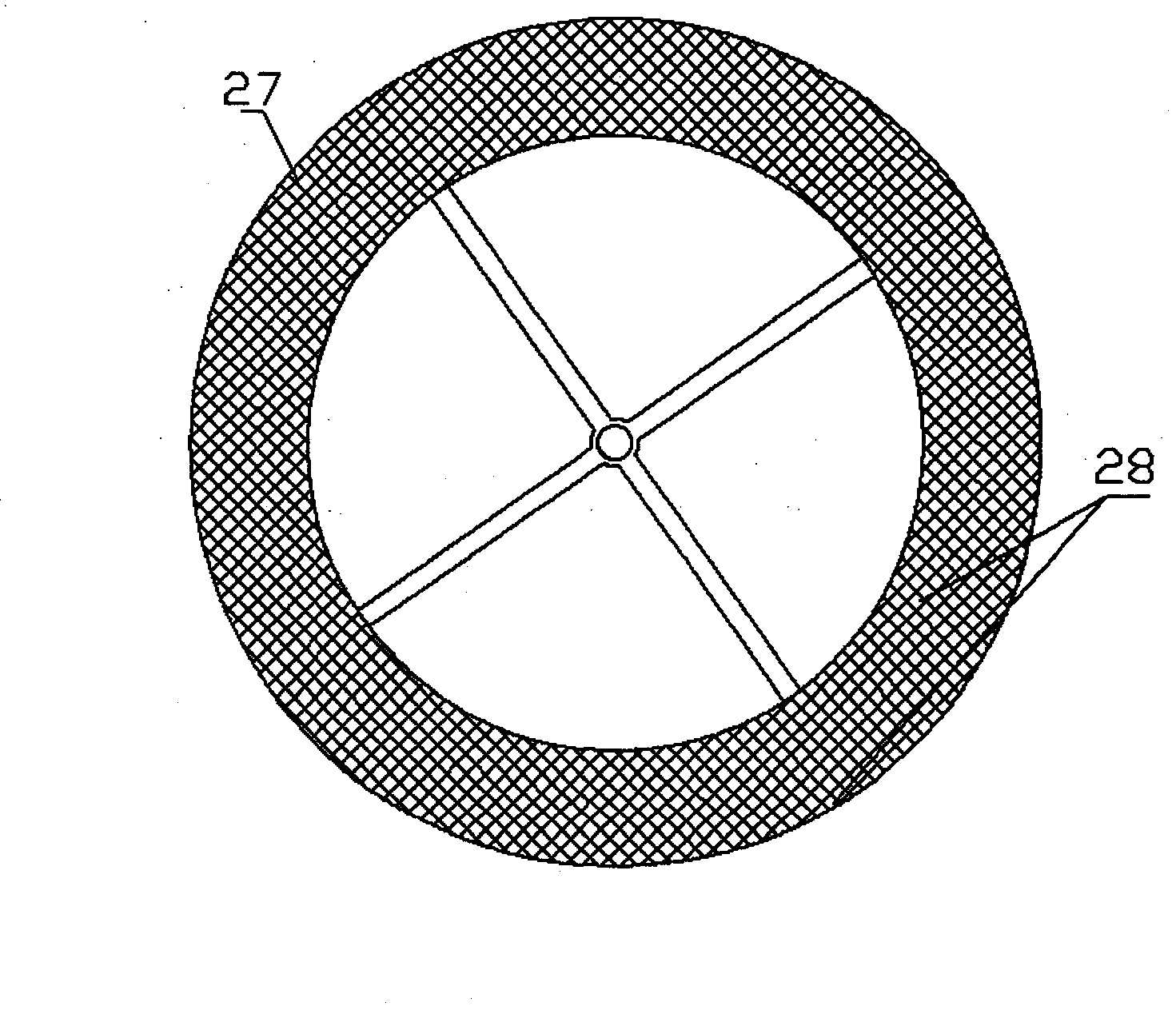
[0017] Embodiment one: in figure 1 ; Figure 9 In the shown embodiment, it is a relatively simple application mode of the present invention on existing helicopters. The connection between the root of the blade 1 and the propeller hub abandons the original swing hinge and pendulum hinge or some elastic elements, and the variable pitch hinge and swash plate etc. are still retained, the rotor has four blades 1, a fairing net cover 28, a circle of annular outer support frame 3, etc., the outer chord of the blade 1 top has an axle, the inner surface of the annular outer support frame 3 Four shaft sleeves are evenly distributed, and are respectively connected with the outer chord of the blade 1 in the form of a shaft and a shaft sleeve, so as to adjust the upward angle of attack of the blade 1; 31 is connected with the bearing at the top of the rotor shaft 10, so that the fairing screen cover 28 can be tilted with the top of the axis line of the rotor shaft 10 as the base point, bu...

Embodiment 2

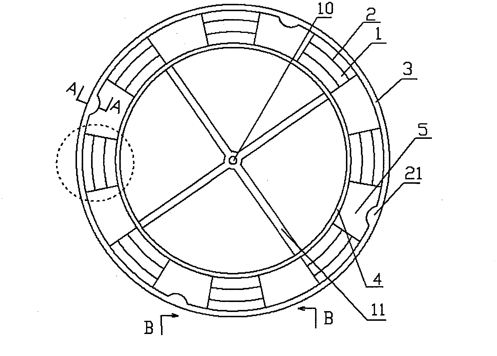
[0019] Embodiment two: if figure 2 ; image 3 ; Figure 4 ; Figure 5 ; Figure 6As shown, this embodiment includes: eight blades 1, four sets of control ring regulators 21, an annular propeller hub 4, an annular outer support frame 3, a rectifying net cover 28, and an inner surface of the annular outer support frame 3. Ring groove 30, there is a blade angle of attack control ring 9 that can move up and down in the ring groove 30, four spoke plates 11, and two wing knives 2 are arranged on each blade 1 to prevent airflow from slipping centrifugally. Four rigid webs 11 are rigidly fixedly connected between the annular propeller hub 4 and the rotor shaft 10 . The paddles 1 are evenly distributed between the annular outer support frame 3 and the annular paddle hub 4, and there are gaps 5 between the paddles 1, and the downwash airflow generated by the paddles 1 in front of the gaps passes through the gaps 5 downward; Figure 4 ; Figure 6 As shown: the blade 1 connected to...


PUM


Abstract

The invention discloses helicopter rotor wings with a commutation net cover and a scheme thereof. The rotor wings are rigid blades and are provided with supports on the outer ends, which relieves an up-down brandishing oscillation of a helicopter; the commutation net cover on the rotor wings solves lifting force difference between two sides of the rotor wings during forward flying, and when the helicopter flies forward, air flow forward does not blast the blades directly, changes directions through the commutation net cover and flows downward, thereby solving the problems of relative deceleration of retreating blades and uneven forces between a left lifting force and a right lifting force; the rotor blades can be designed into any shapes beneficial to reducing impact wave resistance, such as arched saber-shaped blades with sharp blade front edge, which effectively improve maneuverability and flight efficiency of the helicopter; the rotor wings is also beneficial to achieving supersonic velocity rotation, which greatly increases the lifting force and the flying speed of the helicopter. By applying the helicopter with the rotor wings, a theoretical limit that speed can not surpass 420 km per hour can be broken down.

Description

Technical field [0001] The invention relates to the field of aviation, in particular to a helicopter rotor system. technical background [0002] A known helicopter rotor is generally composed of several flexible blades, a hub, a swing hinge, a shimmy hinge, etc., and the blades are connected to the rotor shaft through a hinged manner and the hub. As we all know, the rotor moves in a circle. Due to the radius, when the linear velocity at the tip of the blade is already very high, the linear velocity at the center of the circle is zero! Therefore, the place where the rotor is close to the circumference produces the greatest lift, while the place close to the center of the circle only produces a negligible lift. When the blade moves forward, the relative speed of the blade and the air is higher than the linear velocity brought by the rotation itself; conversely, when the blade moves backward, the relative speed of the blade and the air is lower than the linear velocity brought...

Claims


Application Information

Patent Timeline
Patent Type & Authority Patents(China)
IPC IPC(8): B64C27/32B64C27/467B64C27/54
Inventor 吴新保
Owner 吴新保
Why Eureka
Try Eureka