Eureka AIR delivers breakthrough ideas for toughest innovation challenges, trusted by R&D personnel around the world.

Time-domain imaging method of spaceborne-airborne bistatic synthetic aperture radar

A synthetic aperture radar and bistatic technology, applied in the field of radar, can solve the problems of synthetic aperture radar image distortion, unsatisfaction, and inadaptability

Inactive Publication Date: 2010-05-19
UNIV OF ELECTRONIC SCI & TECH OF CHINA
View PDF0 Cites 11 Cited by
  • Summary
  • Abstract
  • Description
  • Claims
  • Application Information

AI Technical Summary

Problems solved by technology

As a typical shift-variable bistatic SAR system, the geometric relationship of the transmitting / receiving system changes with time. Therefore, the SAR imaging method based on the assumption of linear time invariance, for example, range-multi The Puler algorithm and the wavenumber domain algorithm cannot meet the requirements of this type of bistatic SAR imaging; in addition, even if the shift-variable bistatic SAR imaging point target imaging is realized, the range and azimuth of the shift-variable bistatic SAR imaging The non-orthogonality of the coordinate system still inevitably leads to the distortion of the bistatic SAR image
At present, the imaging algorithm for shift-variable bistatic synthetic aperture radar, especially the imaging algorithm in the star-machine joint mode, is relatively limited. In terms of effective frequency-domain algorithms, almost only the LBF-E algorithm is used, and in the time domain, except for back-projection (BP ) algorithm and variable-scale inverse Fourier transform algorithm, there are few other algorithms
Moreover, the variable-scale inverse Fourier transform algorithm does not consider the influence of space truncation error, so it is not suitable for the imaging of star-machine joint bistatic synthetic aperture radar in large scenes.

Method used


Image

  • Time-domain imaging method of spaceborne-airborne bistatic synthetic aperture radar
  • Time-domain imaging method of spaceborne-airborne bistatic synthetic aperture radar
  • Time-domain imaging method of spaceborne-airborne bistatic synthetic aperture radar

Examples


Embodiment Construction

[0070] The present invention mainly adopts the method of simulation experiment to verify, and all steps and conclusions are verified correctly on MATLAB7.0. The specific implementation steps are as follows:

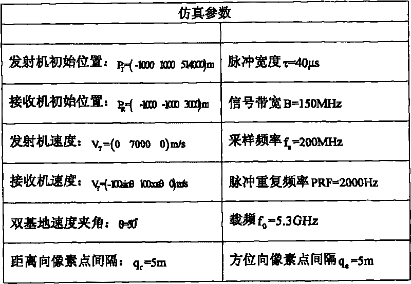
[0071] Step 1. Generate the simulation data of the satellite-machine joint bistatic synthetic aperture radar. The system parameters required for the simulation are as follows: image 3 Shown:

[0072] Step 2. Define the SAR imaging space and initialize the imaging system parameters;

[0073] In this experiment, the unit vector parallel to the velocity direction of the satellite platform and within the ground plane is selected as the first coordinate base ζ of the SAR imaging space v =[0,1,0]; In addition, select the second coordinate base ζ of the SAR imaging space u = [1, 0, 0].

[0074] The system parameters selected in this experiment for initializing the satellite-aircraft joint bistatic SAR imaging method are consistent with those provided in Table 1.

[0075] S...


PUM


Abstract

The invention discloses a time-domain imaging method of spaceborne-airborne bistatic synthetic aperture radar, which aims at the space variant characteristic of a spaceborne-airborne bistatic synthetic aperture radar system, and utilizes an airspace truncation error from history to eliminate an unequal-interval phenomenon of the distortion of the distance position of distance domain data of scattering points after variable metric inverse Fourier transform on the basis of the technology of the variable metric inverse Fourier transform. The unequal-interval phenomenon caused by applying a variable metric inverse Fourier transform algorithm to the imaging of the spaceborne-airborne bistatic synthetic aperture radar is overcome and corrected, so that the imaging of the spaceborne-airborne bistatic synthetic aperture radar in a large scene is realized without increasing overmuch operand. The time-domain imaging method can be applied in the fields of the imaging of the synthetic aperture radar, earth remote sensing and the like.

Description

Technical field: [0001] The invention belongs to the technical field of radar, and in particular relates to a bistatic synthetic aperture radar imaging method in a star-machine joint mode in the synthetic aperture radar (SAR) imaging technology. Background technique: [0002] Bistatic Synthetic Aperture Radar (Bistatic SAR) is a new type of synthetic aperture radar system in which the receiver and transmitter are installed on different moving platforms. As a special mode of bistatic synthetic aperture radar, Spaceborne-Airborne Bistatic SAR adopts the working mode of satellite transmission and single (multiple) aircraft reception. At the same time, it also has the following unique advantages: [0003] 1. The unique "far-send and close-to-receive" mode not only gives full play to the advantages of high satellite station, far-sightedness, and wide coverage, but also maintains a high image signal-to-noise ratio; [0004] 2. Reduce the demand for satellite power, data transmis...

Claims


Application Information

Patent Timeline
IPC IPC(8): G01S13/90
Inventor 张晓玲杨悦师君
Owner UNIV OF ELECTRONIC SCI & TECH OF CHINA
Why Eureka
Eureka Blog
Learn More