Metal armoured optical cable

A technology of metal armor and optical fiber wire, applied in the direction of fiber mechanical structure, etc., to achieve the effect of cost reduction, reasonable structure and superior performance

Inactive Publication Date: 2010-05-12
SHENZHEN ACE ARMORED CABLE CO
View PDF0 Cites 2 Cited by
  • Summary
  • Abstract
  • Description
  • Claims
  • Application Information

AI Technical Summary

Problems solved by technology

The disadvantages are: in the manufacturing process of the above-mentioned protected optical fiber products, in order to make the optical cable meet the design requirements of certain mechanical properties, on the premise of meeting the tensile performance, the structural size of the outer diameter of the optical cable must be increased at the same time Or under the condition of increasing the protective layer, the optical cable can meet certain performances such as lateral pressure resistance and impact resistance
With the rapid development of optical fiber communication, under various conditions of use of optical fiber to districts, buildings, households, office desktops, etc., higher requirements are put forward for the protection of optical fibers. At the same time, optical cable products are required to have a simpler structure and lower cost. , and these are difficult to achieve with current standard products

Method used


Image

  • Metal armoured optical cable
  • Metal armoured optical cable
  • Metal armoured optical cable

Examples


Embodiment Construction

[0018] In order to fully understand the technical content of the present invention, the technical solution of the present invention will be further introduced and illustrated below in conjunction with specific embodiments.

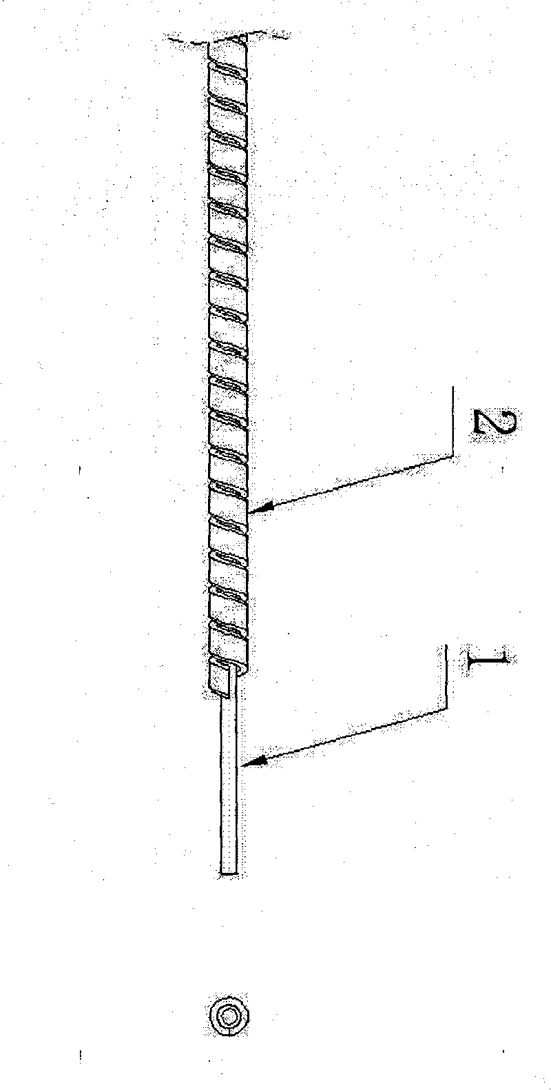
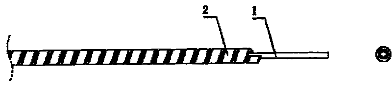
[0019] Metal armored optical fiber cable of the present invention, such as figure 1 As shown, a metal sheath 2 is provided on the outside of the bare optical fiber 1, and the metal sheath 2 is in a spiral shape and wraps the bare optical fiber 1 inside in a surrounding manner.

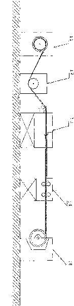
[0020] And this metal armor 2 is installed on the cladding process on the bare optical fiber 1, such as figure 2 The embodiment of the present invention illustrates that the bare optical fiber 1 is placed in the bare optical fiber pay-off mechanism 11, so that the bare optical fiber 1 can be rolled out gradually, and the bare optical fiber 1 enters a fiber pay-off tensioner 12, so that the bare optical fiber 1 is subjected to an appropriate tension. Tension pulls, and then enters...


PUM


Abstract

The invention relates to a metal armoured optical cable. The optical cable can be used to ensure that the optical cable has the advantages of better pressure resistance, low cost and capability of being reprocessed. The bare fibre is covered with a protective armour, and the protective armour is made from metal and is covered outside the bare fibre spirally, thus meeting a certain of mechanical design requirements, such as tensile resistance, side pressure resistance and impact resistance.

Description

technical field [0001] The invention relates to a technique for protecting bare optical fibers, in particular to provide a metal armored optical fiber cable that is resistant to pressure, low in cost and can be reprocessed. Background technique [0002] Optical fiber, referred to as "optical fiber", is a light transmission tool that utilizes the principle of total reflection of light in fibers made of glass or plastic. Because of its small size, small bending radius, and light weight, the optical fiber has a lot of convenience in the use of space. The structure of the optical fiber is a round glass fiber as thin as a hair. It is mainly divided into two parts. The inner layer is called "core." (Core)", usually made of glass; the outer layer is called "Clad", because the diameter of the "core" of the "optical fiber" is only a few "microns" (one millionth of a meter) to tens of "Micrometers", and the diameter of the "fiber shell" is only between one hundred and two hundred "mi...

Claims


Application Information

Patent Timeline
IPC IPC(8): G02B6/44
Inventor 陈俊杰钟剑陈俊生
Owner SHENZHEN ACE ARMORED CABLE CO
Why Eureka
Try Eureka